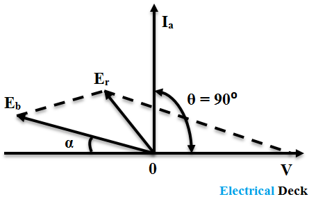
Synchronous Condenser or Synchronous Capacitor :
If a synchronous motor is on no-load and over-excited (Eb > V) then the current drawn by it leads the voltage by nearly 90°. The phasor diagram of the motor at no-load is shown below. Therefore at this condition when a synchronous motor is over-excited it is called a synchronous condenser.
The characteristics of a synchronous motor at this instant will equal to the characteristics of the capacitor. Hence as the capacitor, an over-excited synchronous motor can be used as a power factor correction device.
Power Factor Correction :
As we see in industries most of the motors used are induction motors and load such as lights, fans, heaters, etc will draw lagging currents. These lagging currents will decrease the power factor of the whole unit due to large reactive component. Hence the overall efficiency of the system may decrease.
The power factor correction is possible by using a synchronous motor (operating on no-load with over-excitation) in parallel with induction motors or transformers.
The leading reactive volt-amperes supplied by the synchronous motor compensate for the lagging reactive volt-amperes of other power apparatus. In this way, a synchronous motor as a synchronous condenser is helpful in improving the overall power factor of the system.
The figure above shows the phasor diagram of an arrangement for improving the overall power factor of the electrical system using a synchronous system.
The subscript '1' refers to the induction motor (lagging) load. the subscript '2' refers to the synchronous motor and the subscript 'T' to the total load.


