When there is no load connected to an alternator or synchronous generator there will be no induced voltage in the armature. Hence, the flux present in the air-gap is only due to field ampere-turns. Once an alternator is loaded it starts supplying the load current and there will be an induced voltage in the armature windings.
Since, the induced voltage is of three-phase, the armature current setups its own rotating magnetic field. Now there will be two magnetic fluxes in the air-gap of the machine setup be field and armature winding. The effect of the armature flux on the flux produced by the field ampere-turns is called 'Armature Reaction'.
The flux produced by the armature winding is in such a way that either it opposes or add-up with the field flux causing decrease or increase in the air-gap flux. This causes a change in the performance of the machine. The nature of the effect of armature flux on the field flux depends upon the nature of the power factor of the load. Let us see the effect of armature reaction at different power factor loads.
Armature Reaction of Alternator :
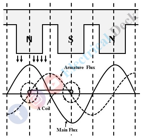
Consider an individual armature coil moving towards the right relative to the field system. Each coil side has the maximum emf induced in it when it is opposite to a pole center.
Armature Reaction of Alternator at Unity Power Factor :
Consider an alternator is supplying to a purely resistive load. The current is in phase with the voltage i.e., unity power factor, and therefore the position of the coil for maximum current will be the same as the position for maximum voltage.
The armature current produces armature flux lags behind the main flux by 90° and it magnetizes the trailing half of the main pole and de-magnetizes the leading half. However, these two effects neutralize each other and average field strength remains the same. The net effect is that the main field is distorted as shown below.
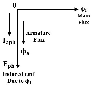
The below shows the phasor diagram at unity power factor load with a phase difference of 90° between the field flux and armature winding flux. The effect on the alternator due to the armature reaction for unity power factor load causes a small terminal voltage drop of an alternator. The effect of armature reaction under unity power factor load is called the 'Cross Magnetising Effect' of armature reaction.
Armature Reaction of Alternator at Zero Power Factor Lagging :
When the load is purely inductive the current lags 90° behind the voltage, and therefore, the coil has to advance 90° (electrical) from the earlier position as shown in the below figure. Hence armature flux lags behind the main flux by a pole.
From the phasor diagram, it is seen that the fluxes due to armature winding and main field winding are completely in opposite direction. Comparing the armature and main fluxes, we see that with an inductive load the effect of armature reaction reduces the main flux.
This results in less emf in generation due to the weakening of main flux. To keep up the same emf, field excitation has to be increased to compensate weakening effect. Since the effect of armature reaction due to inductive load causes demagnetizing of main field flux. The effect is called as 'Demagnetising Effect' of armature reaction.
Armature Reaction of Alternator at Zero Power Factor Leading :
In this case, the current leads the voltage by 90°. so that the coil carries its maximum current by 90° before it reaches the position as shown below.
When the load connected to the alternator is of purely capacitive type. The armature current due to emf induced by main field flux leads by 90° as shown in the below phasor diagram. Thus the armature winding flux and main field flux will be in the same direction and add-up each other.
Hence, in this case, the armature reaction exerts a wholly magnetizing effect due to the addition of both fluxes. This results in greater induced emf, and the terminal voltage of the alternator. To keep up the same emf the excitation to the field has to be reduced. Since the armature flux assists field flux, therefore the effect is called as 'Magnetising effect' of armature reaction.
Nature of Armature Reaction :
The effect of armature reaction on the terminal voltage generated by alternator at various power factor loads is shown in the below figure.


