In concentrated winding, all the coil sides of any one phase are connected in series and grouped together in one slot, and placed under one pole. So that the magnitude and phase difference of the emf induced remains the same throughout the coils of one phase under one pole. The arithmetic sum of the emfs induced in each coil gives net emf induced under one pole of one phase as shown in the below figure.
Distribution Factor :
But, in order to obtain a better wave shape (i.e., more sinusoidal of the induced emf) the coils are divided into a number of slots and distributed one each in three slots per-phase under each pole. The below figure shows the coils of one phase distributed in adjacent slots, and are connected in series. Though the magnitude of the induced emf in distributed winding remains the same, there exists a time-phase difference by a certain angle β° between the coils of one phase under one pole.
The coils are displaced because if we consider the clockwise direction of the alternator as shown above. A similar amount of emf induced in the coil 2-2' as of 1-1' will occur after a time lag of β. Similarly for the coil 3-3' with a time lag of 2β respectively. Hence, the time-phase difference of the induced emf in coils of one phase under one pole depends upon the angular displacement of the slots.
If we represent individual emf induced in coils of the same phase under one pole by phasors. The resultant emf will be phasor sum of all of them as shown above. Here we can see that instead of arithmetic sum for resultant emf as seen in the concentrated winding. It will be a phasor sum for distributed winding. Thus the magnitude of total emf induced will be lesser compared to concentrated type winding.
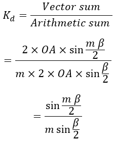
The ratio of phasor sum of emf induced in all coil sides if the winding is distributed to the arithmetic sum of the emf induced in all coil sides if the winding is concentrated is known as the 'Distribution Factor Kd'.
In general, the distribution factor is nothing but the factor by which change (reduction) in emf induced in a distributed winding compared to concentrated winding. It is also known as breadth factor or spread factor or winding factor. It is always less than unity (Kd < 1).
Derivation of Distribution Factor :
Let- n = Number of slots per pole
- m = Number of slots per pole per phase
- Es = EMF induced in each coil side
- β = Angular displacement between slots
- m β = Phase spread angle
- Er = Vector sum of the EMFs induced per phase in one polar group
The below figure shows the magnitude and direction of induced EMFs in coils AB, BC, CD..... of one phase with a successive phase displacement of β°. The resultant emf Er is represented by the phasor AP.
If bisectors are drawn on AB, BC, CD..... they would meet at common point O. The point O would be the circumcentre of the circle having AB, BC, CD..... as chords. From the figure AB = BC = CD = ..... = Er. From △ OAB, if OF is the perpendicular drawn to AB.


