In the last article, we have seen the reasons and conditions for the parallel operation of two or more transformers. Now let us see the parallel operation of single-phase transformers and how the load is shared among them.
Load Sharing by Two Transformers :
Let us consider two transformers A and B are connected in parallel to the supply bus (primary) and load bus (secondary) as shown below. Similarly, two or more transformers can be connected in parallel depending upon the increase in load demand.
Let us summarize the conditions for satisfactory parallel operation of single-phase transformers,- The transformers should be suitable for the supply system voltage and frequency.
- The polarity of the transformer should be ensured that properly connected.
- Transformation or turn ratios of the transformers should be the same.
- The percentage (per-unit) impedance of the transformers should be the same.
- The transformer's ratios of resistance to reactance should be the same.
For satisfactory parallel operation, the transformers must meet the above conditions. Otherwise, under the no-load condition, the localized circulating current will be produced due to unequal induced EMFs in the secondaries to equalize the voltage in each transformer.
Thus when the two transformers have loaded this results in an unequal share of the load with respect to their full kVA output and cause another transformer to overload. The equivalent circuit of the two transformers with unequal induced EMFs is shown below.
However, it is difficult in practice to build such identical transformers. In order to reduce the circulating current, the difference between the voltage ratios of the transformers should be least as possible. This is possible when the difference between the magnetizing current of the transformers is very small.
The circulating current will cause undesirable effects like,- The full kVA output of the transformers cannot be utilized to a full extent.
- It overloads one transformer from the parallel connected group.
- The copper losses in the transformer's windings increases.
With Equal Voltage Ratio :
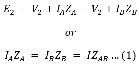
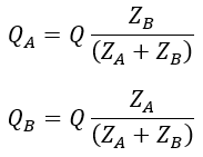
When two transformers operating in parallel having equal voltage ratios (i.e., E1 = E2 = E), the total load current will be divided between them inversely as their equivalent impedance. Since the voltage ratios are the same if we neglect magnetizing currents of two transformers the equivalent circuit referred to as secondary is represented as shown below.


