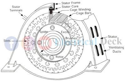
The electrical machine, which generates alternating current and hence voltage is known as 'Alternator or AC Generator or Synchronous Generator'. The following are the major parts of an alternator,
- Stator or Armature (stationary) :
- Stator frame
- Stator core
- Stator winding
- Rotor (rotating) :
- Magnetic poles and field winding
- Slip-rings
- Brush and brush holder
- Spider
- Exciter
- Shaft and bearings
- Stator frame
- Stator core
- Stator winding
- Magnetic poles and field winding
- Slip-rings
- Brush and brush holder
- Spider
- Exciter
- Shaft and bearings
Small alternators are commonly constructed similar to dc generators i.e., with stationary field poles and rotating armature. In large and modern alternators the construction is reverse i.e., the field rotates in the stationary armature system. There are various advantages of the stationary armature and rotating field system. They are,
- Since the armature consists of three-phase winding with high voltage (up to 30,000 V or more). No difficulty is experienced in insulating three-phase winding when it placed on the stator compared to the rotor.
- For large rating alternators, the construction of armature on the rotor becomes more complex. It is easy for coil and phase connections including bracing of winding on the stationary armature.
- Two slip-rings are required to supply dc power when the field is placed on the rotor (a minimum of 3 slip-rings are required for 3-phase armature winding placed on the rotor).
- The field current required to excite field poles is to be supplied at low voltage, thus the requirement of insulation and sparking at the brushes is reduced.
- The weight of field winding is less compared to armature winding, thereby decreasing the weight on the shaft. Therefore the inertia is reduced and makes the rotor run at high speeds.
Construction of Alternator :
Stator Frame :
The stator frame is the outermost part of the alternator. It is made up of cast iron or cast steel or welded steel plates. It encloses all the parts of the alternator from entering dust. It also holds the stator core and winding in proper position and gives mechanical protection to the entire machine.
Stator Core :
The stator core is the stationary part of the alternator. The structure of the stator core is similar to the dc armature core with silicon steel (steel alloy) laminations. The inner periphery of the laminated stator core consists of slots to accommodate three-phase armature conductors. The stator winding (armature winding) is placed in the slots.
The whole structure (i.e., stator core with winding) is held in a stator frame. Since the rotating magnetic field in the alternator continuously cuts the stator core.
The alternating flux causes to induce circulating currents in the core called eddy currents and they cause power loss in the core. To minimize eddy current losses, thin laminated sheets insulated with varnish from each other are used for stator core.
The laminations are stamped out in complete rings for smaller machines or in segments for larger machines. In order to provide efficient cooling, stampings have openings for axial and radial ventilating ducts. Slots are provided on the inner periphery of the stator core. There are three types of slots,
Most of the alternators use open type slots because the coils can be form-wound. It is easy to replace defective coils in case of conductor breakdown. The cost of the insulation prior placed in the slots is less, thus the winding method makes it more satisfactory. But there will be a non-uniform distribution of air-gap flux which produces distortion in the waveform of induced emf.
This is can be overcome by using a semi-closed type of slots but does not permit the use of form wound coils. Totally closed slots are rarely used because of increased winding costs.
Stator Winding or Armature Winding :
Armature winding is made up of insulated copper or aluminum conductor placed in stator core slots. These stationary conductors when cut by the magnetic field emf get induced in them. Basically, the armature of an alternator consists of three-phase winding either in star or delta connection.
Rotor :
The rotor is a rotating part of the alternator. The magnetic poles and field winding are placed on the rotor. The rotor shaft is driven by the prime movers connected to the turbine. The mechanical energy developed in the turbine drives the prime mover and the prime mover drives the alternator shaft.
The field current required to excite field poles is usually provided from a small dc shunt or compound generator (known as exciter) mounted on the same shaft of the prime mover to which the alternator is connected.
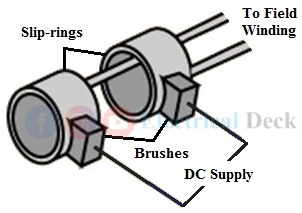
Since the field is a rotating part the exciting current is supplied through slip-rings and brushes. The power rating of the exciter is ordinarily 0.3 to 1% of the power rating of an alternator. Based on construction, the rotor of an alternator is classified into two types. They are,
- Salient pole type or projected pole type.
- Non-salient type or smooth cylindrical type rotor.
i. Sailent Pole Type Rotor :
It is used in low and medium speed alternators. The poles are projected out of the rotor surface with laminations and carry field winding. The ends of the field winding are connected to a dc generator (exciter) through two slip-rings and brushes. This type of construction is well suited to hydraulic turbines or diesel engines.
ii. Non-Sailent Pole Type Rotor :
It is used in very high-speed alternators usually driven by steam turbines, also called turbo-alternators. The rotor consists of smooth solid forged steel radial cylindrical having a number of slots parallel to the shaft for accommodating field winding as shown below.
Slip-rings :
Usually hard drawn copper is used for manufacturing slip-rings. It is in a circular shape mounted on the shaft with insulation between them. Their purpose is to supply excitation current to the rotating field from the stationary brushes.
Brush and Brush Holders :
Brushes and brush holders are stationary parts. The brushes are made up of carbon placed over the surface of slip-rings and are housed in brush holders. Proper contact is maintained between rotating slip-rings and stationary brushes to supply the dc exciting current to the field winding.
Spider :
It is a hub placed on the shaft to which magnetic poles are fitted. It is made up of either cast iron or cast steel.
Shaft and Bearings :
The shaft is made up of cast steel. Its main function is to hold the rotor, slip-rings, and exciter in a proper position. The shaft is supported in bearings. Depending upon the rating and position of the shaft (horizontal or vertical) ball bearings, roller bearings, or thrust bearings are used.


