A transformer is a stationary ac machine used to raise or reduce the voltage levels. There are different types of transformers based on application. A transformer can be single-phase or three-phase. In this article let us see the construction of a single-phase transformer.
A transformer essentially consists of a magnetic circuit or core linked with two distinct windings, primary and secondary placed in a tank and other accessories like a conservator, breather, explosion vent, radiators, and oil level indicator or oil gauge.
Magnetic Circuit or Magnetic Core :
In all types of transformers, the construction of the magnetic core is made up of steel sheet laminations of high silicon content. In order to reduce hysteresis loss and to increase permeability heat-treated silicon laminations are used. The use of laminated sheets is to reduce the eddy current loss.
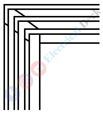
These sheets are being insulated from each other by a thick layer of core-plate varnish. The average thickness of laminations used is 0.4 mm or less based on the frequency. The joints of the core laminations in the form of strips are staggered (also called imbricated) to avoid the presence of a narrow gap right through the cross-section of the core as shown below.
There are three main types of transformers, the type being decided by the disposition of the core. These are,- Core Type (with single magnetic circuit).
- Shell Type (with double magnetic circuit).
- Berry Type (with distributed magnetic circuit).
In core type and shell-type transformers, the laminations are cut in the form of E's and L's as shown below. The laminations are butted (lie adjacent to another) against each other at the joints to increase permeability. The windings are wound on the vertical positioned strips called 'Limbs' while the horizontal portion is called 'Yoke' of the core.
Core Type Transformer :
The construction of the magnetic core of a core type of transformer is in a rectangular shape having two limbs. The primary and secondary windings are interleaved on both limbs to reduce leakage flux. Since it is easy to insulate low voltage winding it is wound near the core limb while high voltage winding is wound over low voltage winding as shown below.
In small core type transformers, cylindrical coils are either circular or rectangular in form. But in large core type transformers, circular cylindrical coils are used. The core is stepped to make a circular cross-section thus reducing the length of the mean turn of winding and I2 R loss, making economical use of copper and core. The core steppings are proportional to the rating of the transformer.
Shell Type Transformer :
In a shell-type transformer, both LV and HV windings are wound on the limb in multiple layers in the form of pancakes. This arrangement is also known as the 'Sandwich' type as shown below. There are three limbs and two magnetic circuits in shell-type construction. The primary and secondary windings (LV and HV) are wound on the center limb with LV winding near the core and HV winding over the LV winding.
The construction of a magnetic core (either core or shell type) is determined by the cost. Practically, both core and shell-type constructions show similar characteristics. Normally shell-type construction is preferred for very high voltages.
The very purpose of the transformer core is to reduce the magnetic reluctance. In other words, it provides the path for the magnetic flux that links with primary and secondary windings.
Primary and Secondary Windings :
The primary and secondary windings of the transformer are usually copper conductors consisting of a series of turns called coils. The coils used for transformer windings are circular or oval-shaped, form-wound cylindrical type.
There are different arrangements of HV and LV windings as shown in core type and shell-type construction, with respect to the core, LV winding is placed nearer to the core.
The primary and secondary winding layers are insulated from each other by paper, cloth, etc. The purpose of the primary winding is to connect the available ac supply, establish the alternating flux, and link the flux with the secondary winding. The purpose of secondary is to establish the required mutually induced emf by providing the number of turns in it.
Tank and Accessories :
The windings and magnetic core of the transformer are immersed in a tightly-fitted sheet metal tank filled with oil. The oil function is two-fold, first keeps the coils reasonably cool, and second, provides additional insulation.
In transformers constructions, more attention and care will be given to the insulation, because the life of the unit almost depends on the quality and durability of these insulating materials.
All the terminals of transformer windings are brought out of the tank through suitable bushings. For moderate voltage, porcelain bushings are used, for high voltages oil-filled or capacitor-type bushings are used. The transformer mountings are fitted on the transformer tank (externally) depending upon the rating of the transformer to protect from faults etc. A few important mountings are,
- Conservator or expansion tank
- Breather or silica gel breather
- Explosion vent or elbow relief device
- Oil level indicator or gauge
Conservator or Expansion Tank :
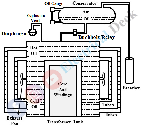
It is a cylindrical oil tank mounted above the transformer and connected to the transformer tank by a hollow pipe with necessary bending as shown above. It contains 50% (half-full) of oil with a full oil level in the main tank. When the transformer is on load, the oil in the main tank gets heated up due to the winding temperature rise, and the volume of the oil increases.
When the oil is cooled, the volume of the oil decreases. This expansion and contraction of the oil will be absorbed by the conservator. Its other function is to reduce the rate of oxidation of the oil. It is usually mounted on the low voltage side of the transformer tank on a supporting frame.
Breather or Silicagel Breather :
It is a small device placed on the atmospheric end of the pipe coming out from the conservator. It mainly consists of silica gel (cobalt chloride) which absorbs moisture.
When the expansions and contractions of the oil are absorbed by the conservator, the air in the conservator leaves and enters accordingly. The air enters the conservator tank through the breather, which arrests or prevents the entry of moisture contents present in the air. This is the simplest and crudent method of preventing the entry of moisture into the conservator or transformer tank.
Explosion Vent or Elbow Relief Device :
It is an elbow relief device, that consists of a large diameter steel pipe fitted on the transformer, and it also contains a thin glass diaphragm at the end as shown above. The diaphragm will rupture to relieve the pressure in the tank whenever the pressure inside the transformer rises to a dangerous point due to an internal short circuit in the winding turns etc.
Oil Level Indicator or Oil Gauge :
Every transformer is provided with an oil gauge to indicate the oil level so that it can easily be read by a person standing on the floor. The oil gauge may be provided with alarm contacts that give an alarm when the oil level has dropped beyond permissible height due to an oil leak, damage to the cooler, or due to any other reason.


