Armature winding is the essential part of any electrical machine (motor or generator). The emf or voltage will be induced in the armature winding in the case of a generator, while it produces torque to rotate the shaft in the case of a motor.
The magnetic flux produced by the field winding is responsible for generating emf and torque in the armature winding. In this article let us discuss armature winding. Some of the basic terms used in the connection of armature winding are,
i. Conductor :
A length of wire used in armature winding placed in the armature slots is called a 'Conductor'. It is made up of copper with one or two or more parallel strands and lies in the magnetic field produced by the field winding.
ii. Turn :
Two conductors connected in series are said to be as one turn. The other end of the two conductors is connected to the commutator segments or connected to the other turns. The emf induced in the two conductors will help each other.
iii. Coil :
The coil is the formation of one or more turns made up of a conductor. A coil consisting of one turn (two conductors) known as a single turn coil and more than two turns (many conductors) known as a multi-turn coil. In a multi-turn coil, the group of wires or conductors are wrapped together with tape. The below diagram shows the term conductor, turn, and coil of an armature winding.
iv. Coil Span or Coil Pitch :
We know that one or more turns form a coil. Two conductors connected in series known as the turn. A coil either in case of single or multi-turn, there are two coil sides. The distance between the two sides of a coil or distance between the two conductors of a turn in a coil is termed as coil span or coil pitch.
v. Pole Pitch :
The distance between the two adjacent pole centers is known as the pole pitch of the machine.
vi. Full-Pitch Coil :
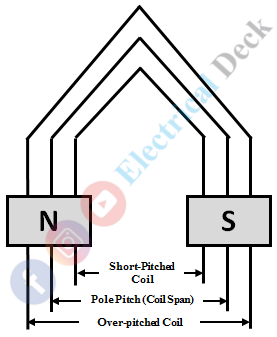
A coil is said to be fully pitched when the coil span is made equal to the pole pitch of the machine. In other words, the distance between the two coil sides of a coil will be equal to the distance between the centers of two adjacent poles. A pole can be of many coils but there will be maximum emf induced in the full-pitched coil since the coil sides of a coil lie under opposite poles.
If the coil span is less than the pole pitch then the coil is said to be a short-pitched coil. Where it is called an over-pitched coil if the coil span is greater than the pole pitch.
The commutation is improved in short-pitched coil, but the emf induced will be less compared to full-pitch. In over-pitched coils, the coil can come under similar poles at an instant while rotating, which makes net emf induced in the coil to zero.
vii. Front Pitch :
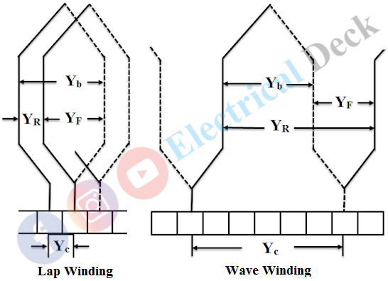
The distance between the second conductor and first conductor of two adjacent armature coils connected in series called front pitch. It is denoted by Yf.
viii. Back Pitch :
The back pitch is similar to that of coil span or coil pitch i.e., the distance between the two coil sides of a coil. It is the distance between the armature conductors, which a coil advance on the back of the armature. It is denoted by Yb.
ix. Commutator Pitch :
It is the distance measured between two commutator segments to which starting and ending terminals of a coil are connected. It is denoted by Yc and measured in terms of commutator bars or segments.
x. Single-layer Winding :
Generally, the two coils sides of an armature coil are placed in armature slots. If the winding in which each armature slot occupies only one coil side then the arrangement is referred to be as single-layer winding.
xi. Double-layer Winding :
Suppose, if the armature winding is made in which two coil sides (two conductors) of different coils are placed in the same armature slot then it is referred to be as double-layer winding. Here the two coil sides are placed one upon another with an equal portion of the armature slot occupied by them.
Armature Winding :
The armature winding is form-wound with properly insulated coils placed in armature slots. Usually, armature windings are symmetrically well-formed distributed throughout the laminated armature core. According to the degree of closure produced by the winding, armature winding can be made in two ways.
- Open coil winding
- Closed coil winding
Open coil winding is a type of winding usually open-circuited i.e., the armature coils are opened. The ends of each coil are brought out of the machine.
In open coil winding the armature winding is not closed until the required external connection is made. Mostly this type of winding is preferred for ac machines (induction and synchronous machines) for connecting armature winding either in star or delta.
Closed coil winding is a type of winding which forms a closed circuit in the armature slots themselves. It means once the winding starts at a point it traverses through whole armature slots and comes back to the starting point, without passing through any external connection.
All the dc machines armature winding employs closed coil winding. The electrical connection to the various armature coils is made through commutator segments and brushes. The closed coil armature windings are of two types,
- Grammer-ring winding
- Drum winding
- Lap winding
- Wave winding
- Lap winding
- Wave winding
In gramme-ring type of armature winding, the conductor is wound around the properly laminated cylindrical core surface. It is an early form of armature winding and used rarely nowadays. The short-comings of ring-type winding are overcome by the more efficient drum-type armature winding.
In drum-type arrangement of armature winding, the armature coils are housed in the armature slots. The coils are wrapped with paper insulation before placed in the slots. The insulation of armature coils in the drum-type winding is easier compared to gramme-ring type. In general, there are two types of drum armature windings.
- Lap Winding
- Wave Winding
Lap Winding :
In lap winding, the two adjacent coils under the same pole are connected are in series, and so on. The series connected coils are then joined to each commutator segment. So that the winding coils formed will overlap each other thus named 'Lap Winding'.
Wave Winding :
In wave winding, instead of overlapping the successive coils, the coils progress forward to another coil with a series connection. The winding so formed will look like a series of waves called 'Wave Winding'. By connecting the winding coils either progressively or retrogressively forming simplex, duplex, and triplex windings. The below figure shows the lap and wave winding of an armature.


