What is Critical Field Resistance of DC Shunt Generator ?
It is defined as the amount of field resistance required to generate emf in the armature winding. (or) The critical field resistance is defined as the field resistance of the generator which holds the rated voltage of it. (or) It is the value of field resistance beyond which the generator fails to build up the voltage if there is a further increase in the field resistance.
Significance of Critical Field Resistance :
By the definition, it can be concluded that for a dc shunt generator to build up the voltage, the total field circuit resistance must be equal to or less than the critical field resistance value.
Run the machine as a shunt generator by connecting the field circuit to the armature terminals. It is to be noted that the only source of excitation for the dc shunt generator is the field current. But, at starting, it builds up voltage due to the presence of residual magnetism.
This voltage causes a small current to flow through the field winding, resulting in the increase in flux per pole and hence the emf generated. Again, this emf causes some more current to flow through the winding and the same process continues till the equilibrium point is reached.
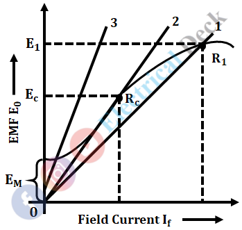
At the equilibrium point, the field resistance line intersects with the open-circuit characteristics curve, and at this point, the generator builds up the maximum voltage. It can be clearly understood by the figure below in which the O.C.C is drawn and some field resistances are taken.
In the above figure, the maximum emf corresponding to the field resistance R1 i.e., line 1 is E1. If the field resistance value is decreased so that the resistance line 2, becomes tangent to the O.C.C curve, then the maximum emf generated corresponding to this will be Ec. The value of resistance given by line 2, which is nothing but the slope of the line is called the critical field resistance.
If the value of field resistance is still decreased as represented by line 3, then the generator will not excite as there is no point of intersection existing between this line and the OCC curve. Hence, there is no emf induced in the generator beyond the critical field resistance.
Determination of Critical Field Resistance :
- Open circuit characteristics is a graph plotted between emf generated and field current. Open circuit characteristics of a dc generator are plotted by using the experimental setup shown below.
- The dc shunt generator is operated at rated speed by decreasing the field resistance in steps from 0 to definite value.
- The readings of ammeter and voltmeter are noted at each step.
- The field resistance is increased until the voltmeter shows a reading 25% more than the rated voltage.
- Here it is noted that even with the increase in field current by decreasing field resistance the emf generated after point b is reduced, it is because of saturation. The O.C.C curve is starting from point 'a' instead of origin O because of the presence of residual magnetism in the generator poles which generates small emf E1, when the dc shunt generator runs at rated speed.
- The field resistance line at no-load is noted. For example, if the field resistance of dc shunt generator is 100 Ω at no-load, then by considering the voltage and current axis as 100V 1A, the field resistance Rf line is drawn.
- The field resistance line cuts the O.C.C curve at point C, concerning to point C on O.C.C the voltage on the y-axis is no-load voltage Eo.
- The line OL is drawn tangent to the O.C.C curve. Taking the value of current axis when tangent line OL passing through the dotted line of no-load emf, critical resistance is calculated. Critical resistance is the slope of tangent line OL given as Rc = Od/Oe ohms.
- The dc shunt generator is operated at rated speed by decreasing the field resistance in steps from 0 to definite value.
- The readings of ammeter and voltmeter are noted at each step.
- The field resistance is increased until the voltmeter shows a reading 25% more than the rated voltage.
What is Critical Speed of DC Shunt Generator ?
Critical speed is defined as the speed at which the given shunt field resistance is equal to the critical resistance. It is the speed at which the shunt generator just fails to build up its voltage without any external resistance in the field circuit. It is denoted by Nc.
Significance of Critical Speed :
If the speed of the dc machine is reduced to a value such that the field resistance line does not pass through the O.C.C then the machine fails to induce i.e., it may not generate any appreciable voltage. The speed at which the generator fails to build up the voltage is known as the critical speed.
Below this speed, the field resistance line does not cut the O.C.C. Hence fails to build up the voltage. Therefore the machine should not be operated below the critical speed as it fails to induce. Hence, it should always be operated above the critical speed.
Determination of Critical Speed :
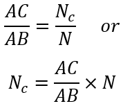
From the figure above, curve I is the O.C.C at a particular given speed N. OB is the tangent line to the O.C.C. OP is the line drawn to represent the given shunt field resistance. Curve II is the O.C.C drawn at the critical speed Nc to be determined. OP is the line tangent to the new O.C.C. If any ordinate AB is drawn intersecting line OP at C then,


