The various applications of ac potentiometer are,- Calibration of voltmeter
- Calibration of ammeter
- Calibration of wattmeter
- Measurement of self reactance or inductance of a coil.
Calibration of Voltmeter :
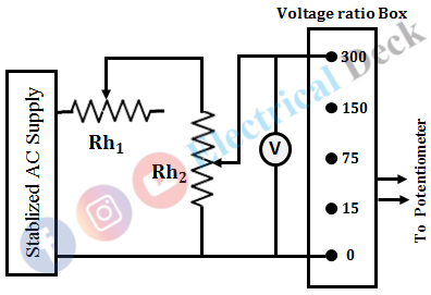
The circuit diagram for the calibration of the voltmeter is shown below. It consists of a stabilized ac supply, rheostats, voltmeter, voltage ratio box, and potentiometer. The basic and important requirement of the circuit is that the input ac supply must not have any fluctuations. Any fluctuation in the supply will have a corresponding change in the calibration of the voltmeter.
Hence, to avoid this a stabilized ac supply must be used. Two rheostats Rh1 and Rh2 are used to have a very precise control so that the voltmeter accurately coincides with the major divisions. A voltage-ratio box is used to reduce the voltage across the voltmeter and applied to the potentiometer.
The potentiometer reads the true value of the voltage. If this value is matched with the voltmeter readings, then the error is zero. However, if these two readings do not match, an error is encountered.
This error may be positive or negative depending on the relative value of the voltmeter and the potentiometer. In order to have greater accuracy, the voltage should be measured near the maximum range of the potentiometer.
A voltage ratio box or two capacitances in series are used along with an ac potentiometer if the voltage to be measured is of medium or high magnitude. Otherwise, an ac potentiometer can be used directly for voltages under 1.5 V.
Calibration of Ammeter :
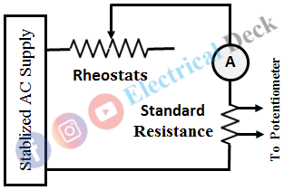
The connection diagram for the calibration of the ammeter is shown in the figure below. The circuit consists of a stabilized ac supply, variable resistor, ammeter, a standard resistor, and a potentiometer. The ammeter is connected in series with the standard, non-inductive resistance of known value R. The potentiometer is connected across the standard resistor.
Let VR be the potentiometer reading which corresponds to the voltage across R. Then the current through R is given by, IR = VR/R. Let I be the ammeter reading. The two values i.e., IR, I will be the same since the ammeter and standard resistor are in series. Since the value of standard resistor is accurately known, accurate calibration of ammeter can be obtained by this method.
Measurement of Unknown Inductance :
The circuit diagram for the measurement of unknown inductance of an inductor or coil is shown in the below figure.
In the figure,- RS = Known standard non-inductive resistance
- RC = Internal resistance of the coil
- L = Inductance of the coil
In this method, two voltage measurements are carried out by switching the DPDT switch to both positions. Let the readings be,- The voltage across RS, v̅R = VR∠θR
- The voltage across the coil, v̅C = VC∠θC
Therefore, the current, impedance, and resistance of the circuit is given by,
The reactance of the coil is,
Hence, the value of unknown inductance can be obtained.
Measurement of Unknown Capacitance :
The circuit diagram for the measurement of unknown capacitance supplied from a single-phase ac supply of known frequency is shown below.
In the figure,- RS = Known standard non-inductive resistance
- RC = Series resistor representing the loss in the capacitor
- C = Capacitance of the capacitor
In this method, two voltage measurements are carried out by switching the DPDT switch to both positions. Let the readings be,- The voltage across RS, v̅R = VR∠θR
- The voltage across the capacitance, v̅C = VC∠θC
Therefore, the current, impedance, and resistance of the circuit is given by,
The reactance of the coil is,
Hence, the value of unknown capacitance can be obtained.
Calibration of Wattmeter :
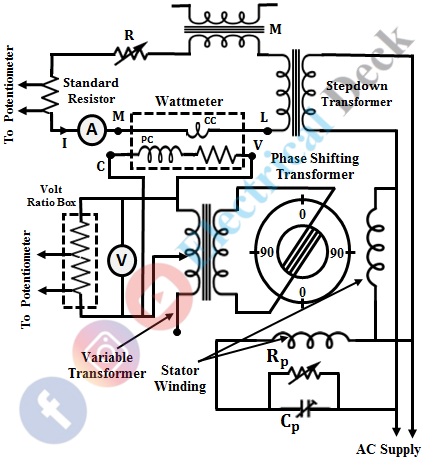
The connection diagram for the calibration of the wattmeter using a polar-type ac potentiometer is shown below.
The current coil of the wattmeter is connected in series with a standard resistor, a variable resistor (or rheostat), an ammeter, and a mutual inductance and it is energized with the supply through a step-down transformer.
The pressure coil is energized through the secondary of a variable transformer whose primary winding is connected to the rotor terminals. The current through the current coil and the voltage across the pressure coil is varied using a variable transformer.
The purpose of voltmeter (V) and ammeter (A) is not to measure the voltage (V) and current (I) but only to ensure that the voltage across and current through the wattmeter are within its range. The voltage across R is measured with the potentiometer and the current (I) through CC is calculated as I = V/R. The voltage across the pressure coil (V) is measured by the potentiometer with the help of a volt ratio box.
The phase angle Φ between the voltage and current can be varied by changing the position of the rotor. Hence, the power to be measured by wattmeter is VI cos Φ. The value obtained by the potentiometer is compared with the deflection of the wattmeter and the wattmeter is calibrated for different combinations of V, I, and Φ. The mutual inductance M in the current coil circuit is to check the accuracy of wattmeter when Φ = 90° i.e., at zero power factor.


