Trivector meter is used to measure the kVAh and kVA of maximum demand. It consists of two meters whose discs are coupled with a special kind of summator through a complicated gearing system. Among the two meters, one is an energy (kilowatt-hour) meter and the other is a reactive kilo volt ampere-hour meter.
The coupling system adds the speeds of the meters vectorially and hence the speed of the summator will be proportional to the kVAh. So, the meter registers the accurate value of kVAh at any power factor. This complicated gearing system consists of five typical gear systems. They are as follows,
kWh Meter Alone Driving a Gear :
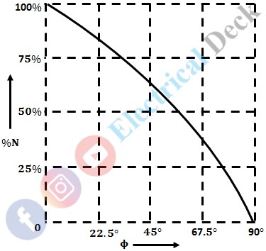
This gear system attains a maximum speed at unity power factory i.e., cos φ = 1 or phase angle, φ = 0° and the speed will be zero at zero power factor i.e., cos φ = 0 or phase angle, φ = 90°. The variation of percentage speed (%N) with φ is shown below.
kWh Meter Speed Reduced Slightly and Reactive kVAh Meter Speed Reduced Considerably :
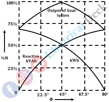
The output of the gear system will be the sum of both speeds. The reduction in the speeds of the meters is done in such a way so as to attain a maximum output speed of the gear system at φ = 22.5° i.e., cos φ = 0.9239. Below shows the % speed variations of all the three speeds with respect to phase angle (φ).
Both kWh and Reactive kVAh Meters Speeds are Reduced Proportionally :
Under these conditions, the variation of % speeds with respect to phase angle (φ) is shown below. The maximum output speed of this gear system will be obtained at φ = 45° i.e., cos φ = 0.7071.
kWh Meter Speed Reduced Considerably and Reactive kVAh Meter Speed Reduced Slightly :
In this gear system, the reduction in the speed of the meter is done in such a way so as to attain a maximum output speed at 67.5° i.e., cos φ = 0.3827. The variations of % speeds with respect to φ are shown in the below figure.
Reactive kVAh Meter alone Driving a Gear :
This gear system attains maximum speed at zero power factor i.e., φ = 90° as shown below.
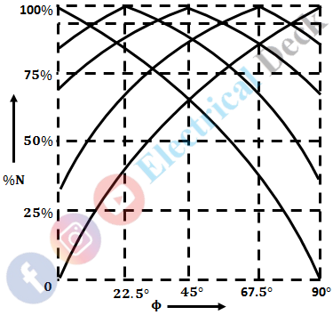
All these five typical gear systems drive a common registering system with the help of a special coupling mechanism that connects the registering system shaft to the drive (i.e., typical gear system's output wheel) which has the highest speed.
Hence, the registering system shaft always moves fast, and thus the variation of its % speed with respect to the phase angle will take the form of peaks of all the five curves i.e., above the dotted line as shown in the figure below. So, the meter reads correctly at almost all the power factors with an accuracy of about 99%.


