Hay's bridge is the electrical circuit used for the measurement of self-inductance. It is an alternating current bridge similar to Maxwell's bridge with small modifications.
The main difference between Hay's bridge and Maxwell's bridge is that Hay's bridge employs a resistance in series with the standard capacitor, whereas Maxwell's bridge uses a resistor in parallel with the standard capacitor.
Construction of Hay’s Bridge :
The Hay's bridge is a modified form of Maxwell's inductance-capacitance bridge. It measures inductance by comparing it with a standard variable capacitance. The circuit diagram of Hay's bridge is shown below.
It consists of an inductor with an inductance L1 and internal resistance R1 in arm AB and non-inductive standard resistances R2 and R3 in arms AD and BC respectively, and a known variable standard capacitance C4 in series with known non-inductive variable standard resistance R4 in arm CD.
Operation and Theory of Hay’s Bridge :
The bridge can be balanced by adjusting the values of R4 and C4. From the above figure,
Under balanced condition, we have,
Equating real and imaginary terms on both sides, we get,
Substituting equation 2 in 1, we get,
Substituting equation 3 in 2, we get,
Now, the quality factor of an inductor is given by,
Substituting equation 5 in 3, we have,
For high Q coils i.e., Q > 10, 1/Q2 is almost negligible. Hence the above equation reduces to,L1 = R2 R3 C4
From the above equations, we can say that for high Q coils the expression for L1 is free from the frequency term. For low Q coils, 1/Q2 cannot be neglected and hence to find L1, the frequency of source is to be accurately known. Therefore, the bridge suits only for the measurements of inductance of high Q coils.
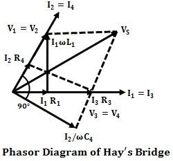
Phasor Diagram of Hay’s Bridge :
The below shows the phasor diagram of the bridge under balanced conditions. By taking inductor current I1 as the reference phasor. It is the current of arm AB, then the voltage drop across R1 will I1 R1 which will be in-phase with I1. Similarly, the voltage drop across L1 will be I1 ωL1 which leads the current I1 with 90°. Now the total voltage drop V1 of arm AB will be the sum of voltage drops across R1 and L1.
When the bridge is balanced, B and D will be at the same potential and there will be a null-deflection i.e., V1 = V2 and V3 = V4, also I1 = I3 and I2 = I4. Therefore, the phasor V2 lies along with V1 with equal magnitude, and the voltage drop I2 R2 (in AD arm) and current I2 will be in-phase with V2.
Also, when the bridge is balanced I4 lies along with I2 and I3 with I1. Similarly, the voltage drop along the BC arm will be I3 R3 and will be in-phase with I3. Thus I3 R3 lies along phasor I3 which is nothing but V3, and V4 will be equal to V3 under balanced condition.
Now the voltage drop in arm CD is the sum of voltage drops across capacitor and resistor i.e., I4 R4 + I4/ωC4. Due to capacitance, the drop I4/ωC4 lags behind the I4 by 90° and I4 R4 lies along with I4. Therefore, the resultant of drop I4 R4 and I4/ωC4 will be V4 (also equal to V3). The resultant of V1 and V3 will be the Vs since Vs will be equal to (V1 + V3) or (V2 + V4).
Advantages of Hay's Bridge :
- The expression obtained for the Q-factor of the coil using Hay's bridge is not a complicated one.
- From the above expression, it can be seen that the resistance R4 is inversely proportional to the Q-factor. Lower the resistance higher the Q-factor. Thus for high Q coils, the value of resistance R4 should be quite small. Hence, the bridge requires the resistance of low value.
- Hay's bridge is suitable for coils whose quality factor is greater than 10 (Q > 10). Also, it gives a simple expression for unknown inductance for high Q coils.
Disadvantages of Hay's Bridge :
The major drawback of Hay's bridge is that it cannot be used for measuring coils having a Q-factor less than 10. We have,
For lower values of Q(<10) the term (1/Q)2 in the above expression cannot be neglected. Hence this bridge cannot be used for coils that have a Q-factor less than 10. For such coils, Maxwell's bridge can be used.


