The earthing of every part of electrical equipment is very important for domestic and as well as industrial applications. Therefore the measurement of resistance of earth connection or earth plate or earth electrode is very important due to following reasons,
- From the safety point of view, every piece of electrical equipment should be properly earthed in the distribution system. By connecting to an earth electrode, all the parts of electrical equipment are at earth potential. This provides a low resistance path for leakage or fault currents in the body of the equipment. Thus, it ensures the safety of the person from electric shock if suddenly he/she touches the equipment.
- The overvoltages induced in the circuit due to lightning discharge or surges or due to sudden change in the voltage usage (voltage spikes), can cause serve damage to the equipment. Thus it is essential to protect the equipment from this excessive overvoltage which can be done by earthing.
- In the case of three-phase circuits, the neutral is earthed to stabilize the potential of other circuits. The power system with neutral grounding is a form of protection for both equipment and personnel.
Hence it is important to take care of the resistance between the earth electrode and the ground surrounding it. The value of resistance should be very low for reliable protection.
However, the resistance depends upon the various factors like shape and material of the electrode, the depth of electrode inserted in the soil, and specific resistance of soil surrounding the electrode which in turn depend upon the moisture present in it.
Therefore the resistance of earth electrodes must be periodically checked to ensure effective earthing. Let us see the method employed for the measuring resistance of the earth electrode offered for the flow of current into the ground.
Fall of Potential Method :
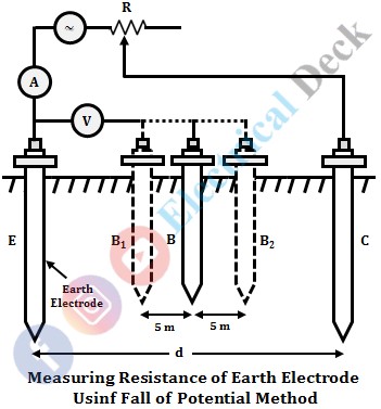
The method uses three electrodes, among which one electrode is under test and the other two are auxiliary electrodes. The below shows the circuit diagram of the fall of potential method.
In the above figure, E is the earth electrode that is under test, and C and B are the auxiliary electrodes. Electrode C is so placed from electrode E that two resistance areas (the resistance area of an electrode is the area surrounding it up to which its voltage gradient exists in the ground) do not overlap each other and B is placed between E and C.
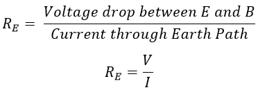
The supply is given between earth electrode E and auxiliary electrode C. Now the voltage drop between electrodes E and B is measured. The expression for measuring earth resistance RE is given by,
By moving electrode B to positions B1 and B2 the resistances area of the electrodes E and C to do not overlap can be checked. The resistance at these positions is measured (i.e., at positions B, B1, and B2) and the mean is computed which is the earth resistance of the main electrode E. Also, the value of resistances obtained at three positions are approximately same in close agreement. The below shows the curve for measurement of resistance at various positions of B from E.
Here, the resistance measured will be correct when electrode B is at a distance from E that resistance RE lies on the horizontal part. Also at low values of resistance, the incorrect positioning of the electrode under test can introduce errors.
Using Earth Tester :
An earth tester is a device used for measuring the resistance of the soil or earth resistance. It is similar to a megger (used for high resistance measurements) with additional features. The instrument directly indicates the resistance offered by earth electrode to the flow of current. The earth tester is provided with three terminals for connecting three electrodes (one earth electrode and two auxiliary electrodes) same as the fall of potential method.
When the generator of the earth tester is driven at its rated speed. The potential and current coils of the earth tester carry the voltage and current respectively depending upon earth resistance. Thus the pointer deflects and indicates the earth resistance which is given by the ratio of potential coil voltage and current coil current.


