In generating stations and substations busbar protection is very important, since when a fault occurs on the busbar it may cause considerable damage and interruption of supply. The protection not only includes the busbars themselves but also the equipment such as circuit breakers, isolating switches, instrument transformers, etc., associated with the busbars.
The stability of the system is affected by the fault in the bus zone. The busbar faults are rare but if they occur on any particular section all the circuit equipment connected to that section must be tripped out to give complete isolation in the shortest possible time. The busbars faults are generally single line to ground faults. The following are the causes for the busbar fault.
- Earth fault resulting due to the failure of support insulator.
- During excessive overvoltages, flashover may occur across the support insulators.
- Errors in the operation and maintenance of switchgear.
- Failure of circuit breakers to clear the fault conditions.
- Accidents due to foreign bodies falling across the busbars.
- Failure of installed equipment.
- A heavily polluted insulator may cause a flashover.
Desirable Features of Busbar Protection :
The following are the desirable features for a busbar protection scheme.- The most important feature of busbar protection is its stability. Even for high faults, the busbar protection should be stable i.e., during the faulty period, the faulty section must be disconnected or it should not operate.
- The other important feature is its speed i.e., whenever high faults or external faults occur then the protection system should get tripped quickly. Typically, the maximum fault clearing time is 100 ms. But with the help of fast breakers, the clearing time is reduced to 20 to 30 ms.
- In the busbar protection system, each circuit breaker should have a separate trip circuit, so that, if a fault occurs at or nearer to any of the circuit breakers then that particular circuit breaker is only tripped.
- In case, if there occurs any mal-operation due to power swings or due to current transformer saturation then, during this period there should not be any operation.
- In order to reduce the interruption of supply in the power system, the protection system should correctly identify the area of faults and should be able to open only the necessary and minimum number of circuit breakers.
Busbar Protection Schemes :
The most widely used schemes for busbar protection are,- Differential protection
- Current differential protection
- Voltage differential protection
- Frame leakage protection
- Backup protection.
- Current differential protection
- Voltage differential protection
Differential Protection :
Current Differential Protection :
The differential scheme of busbar protection is based on the principle of Kirchhoff's current law. According to the principle, under normal working conditions or external fault conditions, the vector sum of currents entering and leaving the bus zone will be equal to zero.
Where, I1, I2, I3, and I4 are the currents in the circuit connected to the busbar as shown in the below figure.
In the differential scheme of busbar protection, the busbar is fed by generators, and power to the loads is supplied by outgoing feeders from the busbar. The current transformers are connected to each circuit of the incoming and outgoing feeders of the busbar and secondaries of current transformers are connected in parallel.
A protective relay coil is connected across the parallel connection of the pilot wires so that the secondary current of all the CTs will flow through the protective relay and the relay will operate.
All the CTs connected in the feeder circuits must be of the same ratio, regardless of feeder load capacity. Under normal operating conditions, the sum of the currents flowing through outgoing feeders from the busbar to the loads is equal to the currents fed to the busbar by the generators i.e., currents entering the busbar are equal to the currents leaving the busbar. Thus no current flows through the protective relay and will remain inoperative.
A current in the relay indicates a fault i.e. when a fault occurs in the protected zone, the currents entering and leaving the busbar will no longer be the same. Therefore, the difference between the currents entering and leaving will flow through the protective relay and initiate the opening of the circuit breaker of each generator and feeder. When there is a fault in the protected section, the vector sum of currents in the circuit connected to the busbar is equal to the fault current.
The current differential protection possesses some difficulties and drawbacks. The main disadvantage of this type of protection is that there will be chances of relay operation during external fault conditions also.
This is due to the saturation of one of the CT of the faulted feeder which causes a differential current to flow through the relay. This flow of current initiates the operation of the relay.
There are certain methods available to overcome the drawbacks of current differential protection.- Using identical current transformers having large iron cores to avoid saturation with maximum fault currents. This method is not applicable because the dc transient component presents difficulties due to its slow decaying nature.
- Using high impedance relay in place of normal low impedance relay. Because a high impedance relay has the capability to discriminate between the internal and external faults better than the low impedance relay. The ratio of relay current during internal fault to relay current during external fault is proportional to the value of the impedance of the relay. For relays of higher impedance value, the ratio is higher.
- Using current transformers with no iron cores are known as linear couplers. This method of protection is known as voltage differential protection which is discussed below.
Voltage Differential Protection :
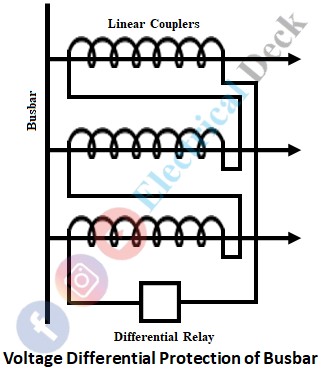
Voltage differential protection is a high-speed form of protection employed to overcome the drawbacks of current differential protection. A special type of current transformers known as linear couplers is used. In linear couplers, there is no iron core and the number of secondary windings is much greater than in the iron core current transformer. The secondary voltage in a linear coupler is proportional to the primary current. The schematic diagram of voltage differential protection for busbars is shown below.
The secondary windings of all the linear couplers on the same bus section are connected in series to the differential relay. The sum of their voltage output is equal to the vector sum of the voltages in the circuits connected to the busbars.
Under normal operating conditions or under the conditions of an external fault, the voltages in the secondary windings add up to zero. Hence, no current flows through the secondary windings and the operating relay.
Under the condition of occurrence of a fault within the busbar zone, there is a resultant voltage in the secondary circuit which results in the flow of current through the secondary winding and the operating relay initiating the operation of the relay to isolate the fault.
Frame Leakage Protection :
Almost all the protection schemes employed for the busbars are designed such that the faults occurred will result in an earth fault. This can be achieved by providing an earthed metal barrier surrounding each bus supporting structure and switchgear from the earth. So that the faults that occur must involve a connection between a conductor and an earthed metal part.
Frame leakage protection is normally applied to small-sized metal-clad switchgear units. The switchgear frame is lightly insulated from its adjacent earthed structural steelwork for this scheme of protection. The below shows the schematic arrangement in the case of a station having an incoming transformer and two outgoing feeders.
As will be seen from this figure, the switchgear framework is connected to the station main earth through the primary of a CT The secondary of the CT is connected to a sensitive frame leakage relay. In the event of an earth fault, currents flowing in the switchgear framework and relay will operate.
The check relay is an earth-fault relay energized from a CT mounted in the incoming transformer neutral earth connection. The contacts of the check relay and frame earth leakage relay are in series so that two independent relays must operate before the trip circuit is completed.
Backup Protection of Busbar :
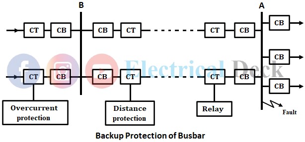
As the power system is divided into various sections or zones for its protection, each section has its particular protective scheme. If a fault occurs in a particular section, it is the responsibility of the nearest circuit breaker of that section to isolate the faulty section.
If due to any reason, the nearest circuit breakers fail to operate, then backup protection should be provided by the adjacent circuit breakers to clear the fault. Backup protection is the simplest of all protection schemes available to protect the buses.
Consider the fault taking place on station A of the system. It is the responsibility of the overcurrent protection at station A to provide protection to station A and isolate the fault. This is the first line of defense. If due to any reason, the overcurrent protection at station A fails to operate, the distance protection at station B provides backup protection to station A which is the second line of defense.


