The feeders in electric power stations and substations are one of the most important elements. According to the statistical information, the majority of faults, occurring on feeders or lines are more. This is due to their large length and exposure to atmospheric conditions.
Several protective schemes are available for the protection of feeders. The protection schemes employed for the transformers and alternators can also be employed for the protection of feeders with slight modifications.
The requirements of feeder protection are listed below.- Short circuits on the feeders create large fault currents and generate a lot of heat which can cause fire thereby causing damage to the system. Therefore, a short circuit on the power system must be cleared by opening the circuit breaker nearest to the fault, all other circuit breakers should be in a closed position.
- If a fault occurs in a particular zone, it is the responsibility of the nearest circuit breaker in that zone to isolate the faulty section. Suppose if the nearest circuit breaker fails to operate, then backup protection should be provided by the adjacent circuit breakers to clear the fault as a second line of defense.
- In order to preserve the system stability without unnecessary tripping of circuits, the operating time of the relay used should be minimum.
Selection of Relaying System For Protection of Feeders :
The following are some of the factors to be considered in designing the relaying system for the protection of feeders.- Economic consdierations,
- Availability of pilot wires,
- Earthing system, and
- Switching stations in between the supply end and the load end of the system.
Economic Consideration :
One of the most important factors while designing a relaying system for the protection of feeders is the economic consideration as there is a number of alternatives to achieve the objective of feeder protection. The protection scheme is said to be uneconomical and unreliable if a proper protection scheme is not selected for the concerned.
For earth fault protection we select overcurrent earth fault protection and it must also be employed with phase protection as one of the distance schemes. Under some circumstances, time graded over current protection will be sufficient and can be selected. Hence the economical design can be made by proper selection of the protection scheme.
Availability of Pilot Wires :
The pilot wires are a unit type of protection only for faults that occur in the same zone. This does not provide backup protection. It is high-speed protection for all types of faults and for finding any fault locations. For short line systems, pilot wire protection is based on differential protection. For long lines and interlinked lines, carrier current protection is used.
Earthing System :
The feeders and lines in the power system have an impact of surges caused due to lightning which damages various equipment in the system. Earthing is a protection type in which a neutral point of electrical supply is usually connected to the earth grounded.
The current flowing in the grounded conductor leads to critical voltages on equipment enclosures. So the grounding conductors and neutral conductors are carefully installed i.e., through electrical regulation. For fault currents, it provides a low resistance path.
Switching Stations in between Supply End and the Load End of the System :
Even though many protective devices are used in a power system the management of the reactive power is weak. Thus to overcome this problem a bank of series and shunt capacitors are used. This provides support to overstressed feeders or lines in the power supply system and achieves optimum utilization and a higher level of stability.
In the feeder, reactive power control is provided to improve the load power factor and load-carrying capacity. By using this capacitor switching the offsetting of inductive content of load current of the receiving or load end is achieved and thus line losses are reduced.
Protection of Feeders :
The feeders are laid generally in the following manner,- Radial feeders
- Parallel feeders, and
- Ring mains.
Radial Feeders :
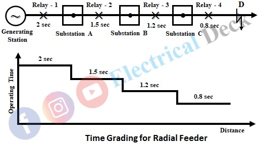
The main characteristic of a radial system is that the direction of power flow in the line can be only in one direction i.e., from the supply end to the consumer end. A time-graded protection system using definite time relays is usually employed for the protection of radial feeders against overcurrents. Here a generating station supplies three substations as shown in the below figure.
At all substations, an overcurrent relay that is independent of operating currents has been used with a definite minimum time setting. The time setting is such that it is least for the relay of the last substation and is maximum for that of the generating station. Relay 4 at substation C has an operating time of 0.8 seconds and there will be a successive increase in the time by 0.4 seconds while moving towards generating station. Normally the time delay step lies between 0.3 sec and 0.5 sec.
In the event of a fault in section CD, for a fault current the definite-time relay of the substation C operates since relay 4 has the minimum time of operation. Thus the circuit breaker operates and only section CD of the system will be isolated.
Suppose for any reason if relay 4 fails to operate, relays 3 and 2 act as backup protection i.e., relay 3 will operate after a time delay of 0.4 seconds. Therefore, it can be observed that if a fault occurs then the relay nearer to that fault will operate first than any other relay.
Advantages of Radial Type Feeder :
- Radial feeders are simple in construction.
- The initial cost required is minimum.
- They are very easy to operate.
- The switching apparatus required is less.
- The size of the conductor required is less.
Disadvantages of Radial Type Feeder :
- Less reliability.
- Continuity of service cannot be maintained.
- The end of the distributor nearer to the feeding point is heavily loaded.
- Due to load variation, high voltage fluctuations occur across the consumers located at the far end of the feeder.
Parallel Feeder Protection :
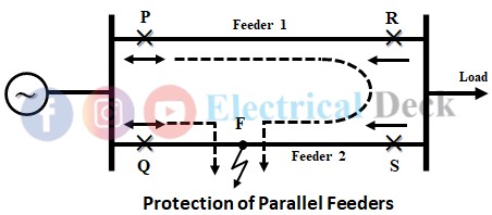
To increase the transmission capacity and where continuity of supply is particularly necessary, two feeders are connected in parallel. So that in case of a fault on any of the feeders only that feeder is isolated and continuity of the supply can be maintained through another feeder. The below figure shows the protective scheme of parallel-connected feeders fed from one end.
In this scheme both the feeders have non-directional overcurrent relays at the source end (at P and Q), the symbol ↔ indicates the non-directional relay, and the relays near the load end (at R and S) are directional relays (reverse power relays).
In case the directional relays near the load side are not provided in conjunction with overcurrent relays, then the required region will not be protected and both the feeders will be tripped out for any fault on any feeder. This is not desired as the healthy feeder is also tripped. Thus the relays at R and S must be directional overcurrent relays.
If a fault F occurs on feeder 2, the power is fed into the fault through two paths PRSF and QF. Here we can see that the power flow at relay R is in the normal direction, but the power flow at relay S is reversed. Thus the relay at S operates instantaneously.
Also due to excess fault current, the overload relay at Q operates. Thus the circuit breaker trips and isolates feeder 2, whereas feeder 1 maintains the continuity of supply.
Protection of Ring Main Feeder :
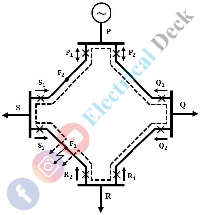
The below shows the overcurrent schemes for the protection of a ring feeder. There are four substations P, Q, R, and S, which are interconnected by alternate routes and fed through one source, thus forming a closed ring.
The substation P is connected to a generating station and supplies power to substations Q, R, and S. There are six-time graded directional relays at both ends of the substations Q, R, and S having their tripping direction when an overload flows away from the substation. The relays at substation P are non-directional time lag overload relays. Since at substation P the power flow will be only in one direction i.e., away from the bus bars.
A fault in any section causes to trip circuit breaker only associated with that section and power flows from the alternate path. If a fault occurs at F1, then the relays at S1 and R2 will trip to isolate the faulty feeder. The relay at R1 will not trip since the fault current is not flowing in its tripping direction, though its operating time is the same as that of R2. Similarly, if a fault at F2 occurs then the relays at S2 and P1 will trip.


