The majority of faults in the power system are transient in nature and may be caused due to switching operations or lightning surges. The power system equipment is directly exposed to lightning strokes which have very high voltage ranging in million volts. Hence, power system equipment is needed to be protected to prevent damage due to heavy voltages. The devices which provide protection to the power system against lightning are as follows,
- Earthing screen
- Overhead ground wires
- Lightning arresters.
The most generally used method of protection of overhead transmission lines against direct lightning strokes is through overhead ground wires. This method is also known as the shielding method. Ground wire protection is one of the efficient methods of protection of overhead transmission lines.
The earthing screen and ground wires can provide protection to the power station and substation only from direct strokes. They cannot provide protection against the traveling waves. The lightning arresters provide protection from both direct and indirect strokes in the form of traveling waves.
Earthing Screen :
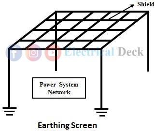
Almost all the generating stations are housed in a structure and substations are of the outdoor type where all the equipment is exposed to natural elements. In order to protect the structure and equipment from direct lightning strokes, there is a need to fulfilling three important requirements, they are interception, conduction, and dissipation. To meet this requirement an overhead shield screen known as Earthing Screen is mounted on top of the total switchyard.
Earthing screen provides protection to the power station and substation from direct strokes. The electrical equipment is protected by the mounted shield of copper conductors all over and by connecting the shield to the ground at two points at least by providing a low impedance path through a resistor. So that the first preference is given to this path for the flow of discharge when there is a lightning stroke towards the station.
For low impedance, there is a need for low resistance, low reactance, and proper clearance from any other conducting object which may provide separate uncontrolled paths to the ground. The setup of the earthing screen is shown in the below figure.
Whenever a direct stroke occurs, the screen absorbs the lightning and provides a path of low resistance by which it is conducted to the earth. Thus, protecting the system from damage. This type of protection system offers better protection against direct lightning strokes. But the disadvantage of this method is that it does not provide protection against traveling waves caused by indirect strokes. Also with an increase in voltage, it becomes tall and uneconomical.
Overhead Ground Wires :
The disadvantage of the earthing screen method can be overcome by using overhead ground wires. It is an effective system for protecting overhead transmission lines from direct lightning strokes. The ground wire used is made up of galvanized steel or ACSR conductor.
The ground wires are always placed above the line conductors which run parallel with line conductors and are grounded through a low resistance path as shown in the figure below.
Whenever a direct lightning stroke occurs, it is intercepted by ground wires and through the low resistance path, it is conducted to the ground. The resistance which provides a path to the lightning surges should be as low as possible for a high degree of protection and this resistance is called tower-footing resistance. It is given by V = IR. As the values of R and V are less, there will be no chance of occurrence of flashover. Thus, the transmission line will be protected.
The ground wire placed and runs on the top of all the towers is at a position such that practically all the lightning strokes towards the transmission lines are intercepted by it. This ground wire is earthed through a low resistance at towers.
It should be ensured that the ground wire used must be mechanically strong that bear sufficient strength. So that there is no breaking of conductor and falling on the line conductors that leads to direct short-circuit fault.
Lightning Arresters :
The efficient way of providing protection to the power system by direct or indirect lightning strokes is through a lightning arrester. It also provides protection against surges that are caused by the traveling waves. A lightning arrester or surge diverter is a protective device that provides protection against high voltage surges on the power system by neutralizing them to the ground before they reach the terminal apparatus connected. The lightning arrester is shown in the below figure.
The lightning arrester consists of two parts. They are,- Spark gap
- Non-linear resistor sets.
Spark Gap :
A spark gap is formed when two electrodes are fixed with a gap between them. The two electrodes are maintained at equal voltage. The spark gap is constructed in such a way that under normal conditions it does not spark over and during high voltage surges, sparkover takes place.
Non-linear Resistor Sets :
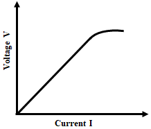
The value of the nonlinear resistor is inversely proportional to the voltage or current. As the current increases the nonlinear resistance decreases. Under normal operating conditions the spark gap remains nonconducting and offers a high resistance path to the flow of current.
When a surge voltage occurs on the line, the sparkover takes place in the spark gap and it offers a low resistance path to the flow of current. Thus, the current follows the low resistance path through nonlinear resistance and neutralizes the fault to the ground.
Since it provides a low resistance path to high current the surge will very quickly move to the ground. Once the surge is neutralized to the ground, the nonlinear resistor offers high resistance for power frequency current. Therefore, the current will flow to the power circuit without any diversion. The V-I characteristics are as shown in the above figure.


