Power transmission lines and associated equipment in the substations are subjected to overvoltage which is generally due to lightning discharge or internal causes (switching operation, sudden changes in load, insulation failure, arcing grounds and resonance).
The travelling waves (high peak voltage surges) caused due to lightning when reaches the terminals of the electrical equipment can cause internal flashover thus damaging the insulation of the windings and insulators.
Hence it is absolutely necessary to provide protection devices at the substations for the protection of equipment against the travelling waves (surges) caused by lightning. Such protective devices are called lightning arresters or surge arresters.
The various types of lightning or surge arresters used for the protection of substations against lightning are, rod gap lightning arrester, horn gap lightning arrester, valve type lightning arrester, expulsion type lightning arrester, metal oxide lightning arrester, thyrite lightning arrester, sphere gap lightning arrester, multiple-gap lightning arrester, oxide film lightning arrester, and electrolytic lightning arrester.
Rod Gap Lightning Arrester :
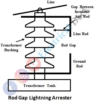
This arrester is very simple and is rugged in construction. It is the cheapest among all the other arresters and requires no maintenance. It consists of two 1 inch metal rods that are placed at right angles to each other with a gap in between them.
One rod is connected to the ground and the other rod is connected to the line circuit. The distance between the rod gap and the insulator should be 1/3 of the rod gap length to avoid any damage to it.
The flashover voltage depends up to some extent on the length of the lower rod which is connected to the ground. If the length of this lower rod is small, then there will be a difference between positive and negative flashover voltages which can be minimized by adjusting the length of the lower rod by 1.5 to 2.0 times the gap length.
The gap between the rods remains open under normal operating conditions. When a high voltage surge occurs on the line, the gaps spark over and it offers a low resistance path for the flow of surge current to the ground. The rod gap arrester is shown in the below figure.
Disadvantages of Rod Gap Arrester :
- The main drawback of this type of lightning arrester is it doesn't interrupt the power frequency follow current after the surge has disappeared or surge voltage becomes less than the breakdown value. This causes a line to ground fault after every discharge of surge voltage by the arrester and initiates the breaker operation to de-energize the circuit to clear the flashover.
- There can be chances of damaging the rods due to heat produced by the spark between the gaps.
- The performance of the rod gap arrester is affected by the polarity of transient overvoltage and atmospheric conditions.
Due to the above limitations, the rod gap arrester is mostly used as backup protection.
Horn Gap Lightning Arrester :
It is used on low voltage lines due to its simplicity. The below shows the schematic arrangement of the horn gap arrester. The horn gap arrester has been shown in one of the lines, but actually, there will be three horn gaps, one for each line.
It consists of two horn-shaped pieces of metal rods separated by a small distance and connected in a shunt between each conductor and earth. The gap between horns is less at the bottom and large at the top.
The figure above shows the horn gap arrangement which consists of a horn gap in series with a resistor R, choke coil L and the apparatus to be protected (transformer). One of the rods of the horn gap is connected to the line and the other is solidly grounded.
Under normal working conditions, the breakdown strength of the gap is more when compared to the normal power frequency voltage and hence the gap does not conduct.
Whenever an overvoltage having a value greater than the breakdown strength of the gap occurs, then the gap conducts and a sparkover (flash) takes place across the gap (i.e., between A and A') at about double the normal working voltage.
The heated air around the arc and the electromagnetic action of the arc cause the arc to travel up the gap. At position BB' the gap is wide and the voltage is insufficient to maintain the arc, therefore the arc is extinguished. The extinguished time is not more than 3-5 sec.
The function of the resistor in series with the horn gap is to reduce the flow of current to a safe value. Since the horn gap is unable to repture currents beyond 10 amperes. The choke coil which is connected in between the system to be protected and the ground of the horn gap reduces the sharpness of the incident wave and does not allow the transients to enter the system to be protected. The impulse ratio of this arrester is 2 to 3.
Disadvantages of Horn Gap Arrester :
- The gap can be bridged by birds.
- The setting of the horn gap is likely to change due to corrosion or pitting.
- The time of operation is comparatively long, say about 3 sec.
Valve Type Lightning Arrester :
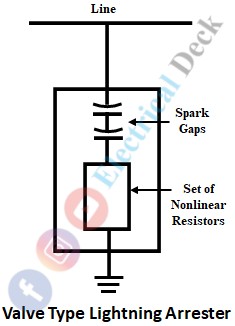
This type of arrester is also known as nonlinear type lightning arrester, which is extensively used on systems operating at high voltages up to 440 kV. Valve-type arrester is divided into two parts i.e., series spark gaps and nonlinear resistors sets. These two are connected in series with each other and placed in a tight porcelain container.
Series Spark Gap :
The spark gap consists of a number of series-connected identical spark gaps. Every spark gap is formed by two electrodes with a fixed gap between them, which are maintained at equal voltage by using additional resistive elements known as grading resistors. The spark gaps are constructed in such a way that under normal conditions it does not sparkover and during high voltage surges, sparkover takes place.
Nonlinear Resistance :
These resistors have a very low resistance under high-frequency surge currents, which decreases the terminal voltage of the surge arrester and under power frequency voltage they have high resistance. The resistance of these nonlinear resistors is referred to as nonlinear resistance. We can say that the resistance of these nonlinear elements decreases with the increase in current through them. They are made up of an inorganic compound such as thyrite or metrosil.
Under normal conditions, the spark remains nonconducting. When a surge voltage occurs on the line, a sparkover takes place in the spark gaps and high current flows to the ground through nonlinear resistors.
These resistors offer very low resistance to the high magnitude surge currents, so the surge will move to the ground very quickly. The nonlinear resistors offer high resistance for power frequency current after the removal of surge on the line. This entire operation takes place within a few μsec.
Expulsion Type Lightning Arrester :
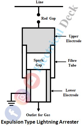
This type of arrester is also known as protector tube or expulsion gap and it is commonly limited to systems operating at voltages up to 33kV. The construction detail of this arrester is shown below.
It essentially consists of,- A tube made of fibre is a very effective gas evolving material.
- An isolating spark gap.
- An interrupting spark gap, which is in series with the rod gap, is enclosed within the fibre tube. This interrupting spark gap is made up of two electrodes, in which the upper electrode is connected to the rod gap and the lower electrode is connected to the ground. There will be one expulsion arrester under each line conductor.
When a surge voltage occurs on the line, the rod gap length will be increased and an arc is produced between the electrodes in the tube. Neutral gas is produced in the tube due to the vaporization of fibre of the tube walls. By the heat of an arc in a short span of time, high pressure will be built up by the evolved gas and the gas comes out of the tube.
At the lower electrode, the gas which is coming out of the tube carries ionized air around the arc. The arc is extinguished at current zero. And due to the strong deionizing effect, the arc will not reestablish. As soon as, the gases have been expelled and the arc is extinguished, the tube is ready for a new operation. There are two types of expulsion arresters. They are,
- Transmission line type, and
- Distribution type.
Metal Oxide Lightning Arrester :
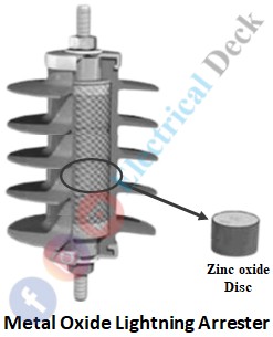
The metal oxide lightning arrester is the most commonly used arrester in modern power systems. It consists of a stack of series-connected metal discs made up of zinc oxide having highly non-linear resistance. Due to its high degree of non-linearity in resistance over a large current range, the arrester eliminates the use of a series gap. Hence the metal oxide arrester is also known as zinc oxide gapless lightning arrester.
It is dimensioned so that the peak value of the phase to ground voltage in normal operation never exceeds the sum of the rated voltages of series-connected discs. Under normal operating conditions i.e., when there is no surge, the arrester offers high resistance (almost infinite) to earth. On the occurrence of surge voltage on the line, the metal oxide surge arrester responds very quickly to the surge voltage by decreasing its resistance.
As the lightning arrester is connected between phase and ground, the very large current due to surge is discharged to the earth. Hence, the surge voltage is safely diverted to the earth and the energy of the surge is absorbed by the arrester. Once the system attains its normal rated voltage, the arrester offers high resistance and acts as an open circuit. Thus leaving the system voltage unaffected at normal conditions.
Thyrite Type Lightning Arrester :
This type of arrester is commonly employed for the protection against very high voltages. Thyrite is a dense inorganic compound that possesses the special property that its resistance varies from high values at low voltages to low values at high voltages.
It consists of discs of 15 cm diameter and 19 mm thickness. The surface of the discs is sprayed by a metal layer so that there exists electrical connectivity between the discs and all the discs are enclosed in a glazed porcelain container.
On the occurrence of lightning, the surge voltage causes the gap to break down and the resistance decreases to a low value. Thus the travelling wave is discharged to the ground. After the successful discharge of surge voltage i.e., when the line voltage becomes to normal power frequency voltage, the thyrite regains its original property by offering high resistance to the normal power frequency voltage.
Sphere Gap Lightning Arrester :
The sphere gap lightning arrester is shown below. In this type of lightning arrester, the air gap is provided by two similar spheres A and B. Sphere B is grounded while sphere A is connected to line Y. The distance between the two spheres can be adjusted with the help of a gauge. A choking coil is inserted between the phase winding Y of the transformer and sphere A, for reflecting off any overvoltage surges that might attempt to enter the transformer winding.
The minimum air gap is set so that a discharge does not take place at ordinary working voltages but at predetermined excess voltages an arc is set up. This arc will travel up the spheres as the heated air near the arc tends to rise upwards. The arc will keep on travelling upwards and lengthening till it is broken automatically. The impulse ratio of the sphere gap lightning arrester is unity.
Multi Gap Lightning Arrester :
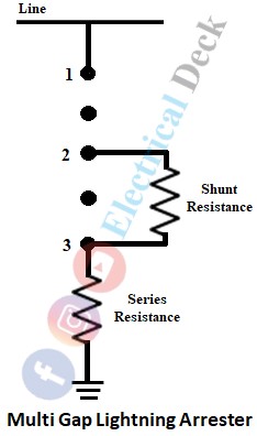
Multi gap arresters are used in systems in which the system voltage is not more than 33 kV. The construction of a multi gap arrester is shown in the figure below. This type of arrester consists of a series of metallic cylinders which are generally made up of alloy or zinc. These cylinders are insulated from one another and are separated by an air gap of small intervals.
As shown in the figure above, the first cylinder i.e., cylinder 1 is connected in series with the line and the last cylinder i.e., cylinder 3 is connected to the earth through a series resistance.
As the series resistance limits the power arc, the degree of protection against the travelling waves of the multigap arrester is reduced. This difficulty is overcome by including a shunt resistance in some of the gaps, such as between cylinders 2 and 3 as shown in the figure above.
Working :
When the system is healthy, point 1 will be at normal supply voltage and point 2 will be at earth potential. Under this condition, it will not be possible for the supply voltage to break down the series gap. But, under the faulty condition i.e., due to overvoltage, the breakdown between gaps 1 and 2 occurs and the large fault current will flow through the shunt resistance. After the surge is over, there will be no arc between gaps 2 and 3 and the power which is left, will follow the path from shunt and series resistance to earth.
Hence, the two resistances will now be in series with each other and will limit the remaining power due to which a small amount of current will be left. This current will not be able to maintain the arc between gaps 1 and 2 and hence the system will again restore to its normal condition.
Oxide Film Lightning Arrester :
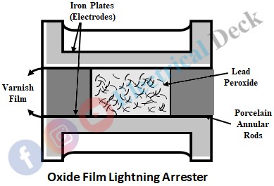
The oxide film arresters use certain dry chemicals that change their property from a good conductor to an insulator on the application of heat. For example, lead peroxide which has a specific resistance of 1 ohm per inch cube at ordinary temperature, is converted to red lead at about 150°C, its specific resistance being then of the order of 24 million ohms per inch cube.
The below shows the oxide film arrester. The actual arrester consists of a number of cells. Each cell consists of two Iron electrodes coated with varnish on one side. The electrodes are separated by an annular ring. The space so formed between the electrode is filled with lead peroxide power Each cell can be used for voltages in the range of 250-300 Volts.
When an overvoltage occurs on the line the varnish film breaks down at one or more points in every cell and discharge passes through the lead peroxide, which is converted to red lead due to heating. As soon as this happens the discharge will cease.
The power current cannot flow to the ground because of the high resistivity of the red lead. Gradually however the whole of the lead peroxide will be converted into a red lead, but the dimensions of the cell are so chosen that it takes a number of years before it becomes useless for further service.
The advantage of this arrester is that it does not require daily charging and can be used in remote locations where daily supervision is not required. But the drawback is that it is not so sensitive to lower types of transients because the action of this lightning arrester depends upon the breaking of the varnish film.
Electrolyte Lightning Arrester :
The electrolyte arrester uses a thin film of aluminium hydroxide deposited on the aluminium plates kept in an electrolyte. It operates on the fact that the resistance of the plate decreases with an increase in voltage and offers negligible resistance to the voltage above the critical value. At low voltages i.e., under normal operating conditions, the plate offers high resistance.
When the voltage on the line increases beyond the critical breakdown voltage, it causes a puncture and current flows to the earth. After the discharge of surge voltage, the arrester again offers high resistance to normal power frequency voltage. The total critical value of the voltage of the arrester can be increased by increasing the number of films. But this type of arrester needs daily supervision and the film needs to be changed whenever destroyed.

