Ungrounded Neutral System - its Behaviour & Disadvantages

The ungrounded neutral system is a neutral system in which there is isolation between neutral and ground i.e., there is no electrical connection between neutral and ground. Hence the ungrounded neutral system is also called an isolated neutral system or free neutral system or insulated neutral system.

Ungrounded Neutral System :

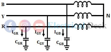
A simple 3-phase system with ungrounded is shown in the below figure. In reality, there exists a capacitive effect between one conductor to another and the line conductors also have a capacitance effect with the ground too. Thus capacitive currents flow in all the phases of the system.

Ungrounded Neutral System

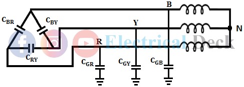
In the above figure, the capacitors between conductor and ground are star-connected, whereas the capacitors between each conductor are delta connected. The capacitance value of the delta-connected capacitors can be neglected as they have no effect on the earth circuit.

During Normal Condition :

In normal operating conditions, the system is balanced and the capacitances to the ground are assumed to be equal i.e., CGR = CGY = CGB = CEC, where CEC is the capacitance of each capacitor to ground. From the above figure, it was said that the delta-connected capacitors can be neglected as they have no effect on earth, if so done then the figure above gets modified as shown in the below figure.

Ungrounded Neutral System

As the capacitance becomes equal in every conductor then the phase voltages also become equal (in magnitude) i.e., VGR, VGB, VGY, and hence the capacitance currents also become equal to Vph/Xc.

VCR = VCB = VCY (magnitudinally)
IGR = IGY = IGB = Vph/Xc
Ungrounded Neutral System

Under the normal operating conditions, the system is balanced i.e., all the line phase voltages will be equal in magnitude and have a phase difference of 120°. As the shunt capacitors of all the phases are the same, the corresponding charging current will also be equal. The currents will be equal in magnitude and have a phase difference of 120° as the system is balanced. Hence, the sum of these currents will be equal to zero.

i.e., IR = I > 0
IY = I > -120°
IB = I > -240°
∴ IR + IY + IB = 0

We know that, the neutral current is,
∴ IN = IR + IY + IB = 0
Hence, there is no current flowing through the ground and therefore, the neutral and ground will be at the same potential under normal operating conditions.

During Fault Condition :

Let us assume that an L-G fault occurs on the system at some point F with the L-G fault in R, the potential of the R phase gets equal to ground potential, and due to this a short-circuit occurs in capacitance of line (i.e., CGR). Therefore no current flows through CGR.

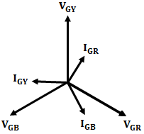
The capacitive currents IGB and IGY flow through the phase lines B and Y respectively. The driving voltages of IGB and IGY are VGB and VGY respectively, moreover note is to be taken that VRY and VRB are line voltages. The two currents flowing i.e., IGY and IGB are having capacitive paths. Thus IGY leads VRY by π/2 and IGB leads VRB by π/2. The fault current IF in R is nothing but the sum of the two currents IGB and IGY.

Ungrounded Neutral System

So under an earth fault in phase R,
Ungrounded Neutral System
Since phase voltages are equal, say equal to Vph, and capacitances from line-to-ground are equal, say equal to XC. So capacitive currents of healthy passes (IGB and IGY) under fault conditions become √3 times their respective values under healthy conditions. Therefore, the fault current IF is nothing but the phasor sum of currents IGB and IGY.
Ungrounded Neutral System
Where, Ic is the charging current under normal conditions hence the capacitive fault current IF becomes 3 times the normal per phase capacitive current. As the capacitive fault current is small in magnitude with which it can't operate protective devices. Hence, the ungrounded neutral system is not so efficient in providing protection against earth faults.

Disadvantages of Ungrounded Neutral System :

The effects of ungrounded neutral on system performance are,
  • In an ungrounded system, the phenomenon of arcing grounds due to earth faults commonly occur and due to arcing grounds, there may be insulation breakdown.
  • Due to arcing grounds in an ungrounded system, a temporary fault can shift into a permanent fault.
  • When an earth fault occurs in an ungrounded system, then there will be an increase in the voltage of the healthy phases above the earth by √3 times its normal value, due to which the insulation of all machines and equipment connected to the system will experience severe stress.
  • The ungrounded system cannot be provided with adequate protection as in this system the earth fault cannot be sensed easily. As the fault current will not be sufficient to initiate the operation of the protective relay. Hence, the earth fault relay in this system is more complicated.
  • The capacitive current in the faulty phase of an ungrounded system will rise to 3 times that of the normal per phase capacitive current.
  • In an ungrounded system, the overvoltages due to induced static charges and lightning surges will not be discharged to the ground and will be remaining in the system itself because of which the system equipment may get damaged.
  • The actual fault location in an ungrounded system cannot be located. As in this system during an earth fault, the capacitive current in each phase will become unstable, as these capacitive currents will be contributing to the fault current. Because of an unbalanced capacitive current, it is not possible to install a discriminative type of fault indicator, but a neutral discriminative indicator can be connected across this type of system which will only give a warning on the occurrence of an earth fault without indicating the actual fault location.
Due to these disadvantages, the ungrounded system is not being used in the modern 3-phase system.

Do not enter any spam links and messages

Post a Comment (0)
Previous Post Next Post