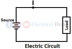
A circuit is basically a closed path in which either electric current or magnetic flux flows. Although electric and magnetic circuits looks similar they are not analogous in all aspects. In this article let us see what is an electric and magnetic circuit and the differences between an electric circuit and a magnetic circuit by comparing various factors like current, voltage, EMF, MMF, reluctance, magnetic flux, etc.
What is an Electric Circuit?
An electric circuit is a closed path or network in which electric current or electrons flows. An electric circuit mainly consists of a source (battery, generator, cell) that supplies electric power, a conductor in which current (I) flows and load (lights, fans, appliances, etc.) which consumes power, and other components like resistors, capacitors, inductors, switches, etc.
The different types of electric circuits are series, parallel and series-parallel circuits. In a series electrical circuit, there is only one single path for the flow of current. In this type of circuit, all the components are connected one after the other. In a parallel electric circuit, the current has multiple paths to flow through.
What is an Magnetic Circuit?
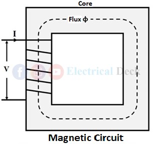
A magnetic circuit is a closed path followed by magnetic lines of force. The best examples of magnetic circuits are transformers, dc machines, synchronous machines, induction machines, etc., the operation of these electrical machines relies upon their magnetic circuits.
A magnetic circuit generally consists of magnetic material having high permeability like iron, soft steel, etc. This magnetic material is called a core and is wound with a winding that creates magnetic flux in the core. The magnetic flux in a magnetic circuit starts at a point and ends at the same point by passing through the circuit path as shown below.
Magnetic circuits are generally two types series and parallel magnetic circuits. In series magnetic circuits, there will be only one path for the flow of magnetic field lines i.e., total magnetic flux has to flow through one path which is similar to a series electric circuit. In parallel magnetic circuits, there is more than one path for the flow of magnetic field lines comparable to a parallel electric circuit.
Comparison Between Electric and Magnetic Circuits :
| Parameter | Electric Circuit | Magnetic Circuit |
|---|---|---|
| Definition | An electric circuit is a closed-loop network through which electric current (electrons) flows. | A magnetic circuit is made up of one or more closed paths of magnetic field lines or magnetic flux. |
| Circuit Quantities | The basic electric circuit quantities are current, voltage, EMF (electromotive force), resistance, capacitance, inductance, electric power, etc. | The basic magnetic circuit quantities are MMF (magnetomotive force), reluctance, magnetic flux, magnetic permeability, etc. |
| Ohm’s law | Ohm’s law for electric circuits is given as, Current = EMF/Resistance or Voltage/Resistance | Ohm’s law for magnetic circuits is given as, Magnetic flux = MMF/Reluctance |
| Units | Electric current (I) is measured in Amperes. | Magnetic flux (Φ) is measured in Weber. |
| Resistance and Reluctance | Electrical resistance is the measure of opposition offered by an electric circuit to the current. Resistance (R) = ρl/a Ω | Magnetic reluctance or magnetic resistance is the opposition offered by a magnetic circuit to the magnetic flux. Reluctance (S) = l/aµ AT/wb |
| Driving Force | In an electric circuit, EMF (electromotive force) is the driving force that produces a potential difference or voltage for the flow of current. It is measured in Volts. | In the case of magnetic circuits, MMF (magnetomotive force) is the driving force that gives rise to magnetic flux. It is measured in Ampere turns (AT). |
| Conductance and Permeance | Electrical conductance is the measure of the ability of a circuit to conduct electric current. It is given as, Conductance (G) = 1/Resistance | Permeance is the measure of ease in the flow of magnetic flux. It is given as, Permeance (µ) = 1/Reluctance |
| Density | Electric current density is the measure of electric current per cross-sectional area. It is given as, Current Density (J) = I/a A/m2 | Magnetic flux density is the number of magnetic field lines passing through a unit area. It is given as, Magnetic flux Density (B) = Φ/a Wb/m2 |
| Field Intensity | In an electric circuit, there exists an electric field whose intensity is given as, E = V/d | In a magnetic circuit, there exists a magnetic field whose intensity is given as, H = NI/l |
| Nature of Current and Flux | The flow of current in the electric circuit is actually the flow of electrons in the conductor. | In magnetic circuits, the magnetic flux actually doesn't flow but it set-ups (basically molecular poles are aligned). |
| Variation of Resistance and Reluctance | The resistance of an electric circuit remains almost constant since resistance depends upon the resistivity of a material (ρ), length, and area which remains almost constant. However, ρ may vary slightly when temperature changes due to which there will slight change in resistance. | The value of reluctance in a magnetic circuit varies with the variation of magnetic flux density (B) since μr changes with the change in B. |
| Drop | In electric circuits, there will be a voltage drop due to the resistance offered by the circuit. It is given by, Voltage drop = IR | In magnetic circuits, there will be an MMF drop due to the reluctance of the magnetic field path. It is given by, MMF drop = ΦS |
| Energy | The energy in the electric circuit depends upon the current flow. Energy is expended continuously, so as long as the electric current flows. | No energy is expanded in a magnetic circuit once magnetic flux is set up. Only a small amount of energy is required for the generation of magnetic flux. |
| Insulator | The perfect insulators for electric circuits that opposes the flow of electric current are air, glass, mica, wood, etc. | In practice, there is no perfect insulator for the magnetic flux since it can even be set up in non-magnetic materials like air, rubber, glass, etc. |
| Applicable Laws | Ohm’s law, KVL (Kirchhoff voltage law), and KCL (Kirchhoff current) are followed in the electric circuits. | Ohm’s law, Kirchhoff’s MMF law, and Kirchhoff’s flux law are followed in a magnetic circuit. |
| Field Lines | The electric field lines or current flows from the positive charge to the negative charge i.e., from the positive terminal to the negative terminal in the electric circuit. | The magnetic field lines in a magnetic circuit start from the north pole and end at the south pole. |


