This test is similar to the no-load test performed on a transformer. The purpose of this test is to determine the no-load losses, no-load power factor, and constants Ro and Xo of the equivalent circuit.
The no-load losses include frictional windage loss, core loss, and a small copper loss in the stator winding. As the slip at no-load is very small and negligible, the rotor copper loss is negligible as the rotor current at no-load is very small and neglected.
The figure above shows the connection diagram and equivalent circuit of the motor at no-load. The normal voltage is applied to the stator winding and the rotor is allowed to rotate freely without any mechanical load on its shaft. Two wattmeters W1 and W2 measure the power input to the motor.
Since the motor is not supplying any load, the no-load current is small and stator copper losses are negligible. The input power, Wo equals mechanical and core losses. To be more accurate the stator copper loss at no-load current should be deducted from the input when calculating the above losses.
Calculation of No-Load Test of Induction Motor :
Let,- Wo = Power input.
- V1 = Applied voltage per phase.
- Io = Applied current per phase under no-load conditions.
Then the no-load power factor is,
Where,- IW = Working component of no-load current Io.
- Iμ = Magnetising component of no-load current Io.
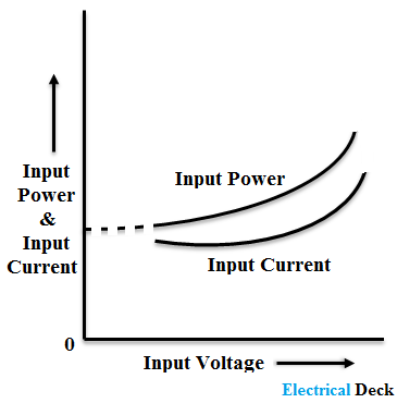
The no-load losses for different voltages are plotted as,
The below table helps you to note down the readings while performing the no-load test on the induction motor. For easier calculation of no-load losses and power factor.
| S.No. | Stator Voltage (V1) | Stator Current (Io | Rotor Current (Ir) | Wattmeter Readings W1 and W2 | Power Input (Wo) |
|---|
| Readings observed from the test> |
But there is a thing you have to remember while performing the no-load test on an induction motor, i.e., changes in speed, power factor, stator current, and rotor current due to fluctuations in applied voltage.
When there are changes (fluctuations) in the applied voltage the readings noted from the test will be more accurate. Hence it also increases the accuracy of the calculations made from the test.


