It is important to monitor current and voltages at the substations and generating stations which are at high values. In dc circuits it is easy to measure large currents by adding suitable shunts to the low range ammeters. Whereas in alternating supply it is difficult to measure large currents and it is dangerous to the operator while working with a system carrying large currents (more than 100A).
For this purpose, an instrument called 'Current Transformer' is used for measuring large currents. A current transformer is also called an instrument transformer with an accurate current ratio of primary and secondary windings. Let us see the construction of the current transformer.
Construction of Current Transformer :
Large alternating currents that cannot be measured directly by normal ammeters or by wattmeters current coil to measure power can be done by using a current transformer. Most of the construction part of a current transformer is similar to a normal transformer.
Basically, it is a step-down transformer (with respect to current) consisting of two windings, primary and secondary without any electrical connection between them. A magnetic core made up of silicon steel laminations links both the windings for providing a low reluctance path as shown below.
The primary winding of a current transformer is wound with a few turns (one or more) of a thick cross-sectioned conductor. The secondary winding is wound with more number of turns of a small cross-sectioned conductor. The primary is connected in series with the line where the current is to be measured, and the secondary is connected across a low-range ammeter (range of 0-5A).
Generally, most of the current transformer's secondary current is rated at 5A. Depending upon the construction there are two types of current transformers used for measuring large currents.
Wound Type Current Transformer :
As the name suggests in wound type current transformers both primary and secondary windings are of wound type with a suitable number of turns. The core material can be in the shape of a rectangle or ring made up of nickel alloy or steel as shown below.
In a ring-type core structure, the secondary winding is wound on the inner core of the bakelite former. Over the secondary winding, the primary winding is wound on the outer core with suitable insulation between the two windings.
Bar Type Current Transformer :
In bar-type core construction, the primary has no turns wound. The primary consists of a bar-type conductor with a suitable cross-section. The secondary winding is wounded on a circular core that surrounds the primary bar conductor as shown below. The paper insulation is kept on the bar i.e., between the primary and secondary.
The distance between the two windings is kept very small to reduce flux leakage. So measured readings are obtained at high accuracy. The current transformer connected to a small line voltage system uses tape or varnish as insulation. In high line voltage systems oil-immersed current transformers are used.
Working of Current Transformer :
The working or operation of a current transformer is similar to that of a normal two-winding transformer. When large currents pass through the primary winding, it induces small currents in the secondary winding (depending upon the turns ratio).
These small currents in the secondary winding are then measured by the low-range ammeter connected across it. In a current transformer, there exists an inverse ratio relation between the current and the number of turns in the primary and secondary windings.
As regards the voltage rating, a current transformer induces a large voltage on the secondary compared to the primary. Hence, it acts as a step-up transformer with respect to the voltage.
Let,- N1 = Number of primary turns
- N2 = Number of secondary turns
- I1 = Primary current
- I2 = Secondary current
For a transformer, the transformation ratio is given as,
Therefore, once the current ratio of the current transformer is known then we can determine the line current on the primary side by measuring the current on the secondary side.
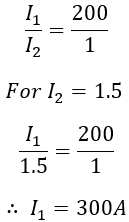
For example, a current transformer has a ratio of 200:1. If the ammeter on the secondary winding is read 1.5 amps i.e, I2 = 1.5A. Then the primary current or load current I1 is given as,
Here, we can also say that the current transformer has a primary and secondary turn ratio of 1:200. Also, the voltage in the secondary winding will be 200 times the primary voltage.
Why CT secondary should not be open?
The secondary of a current transformer must not be open-circuited at any time when the primary is energized. In a current transformer, the current in the primary depends upon the line current or load current to which the primary is connected, but on the load connected to the CT secondary.
Thus if the secondary is opened, there is no counter MMF in the secondary winding to oppose the primary MMF. Now, the whole primary current acts as a magnetizing current and induces large voltages in the secondary.
This causes excessive core losses and produces excessive heat. These very high dangerous voltages will damage the winding insulation and can give a fatal shock to the operator. Thus a CT must not be opened in working condition, it must always be earthed.


