Generally, transformers are used to transfer generated voltage at the generating stations to the various loads. Transformers do this by stepping up the voltage at generating stations and transferring this high voltage to the load centers.
At load centers, the transformer step-downs the voltage levels and sends them to the various domestic and industrial loads. In this transmission process, we have to ensure that the voltage being transferred should be at the correct levels. Thus continuous monitoring of this high voltage measurement must be done.
What is a Potential Transformer?
For measuring high voltages at generating stations and at load centers there must be a need for a special measuring device that cannot be done by normal voltmeters.
A potential transformer is a measuring instrument used for measuring high voltages in a transmission and distribution system. Basically, it is a step-down power transformer, that decreases the voltage levels at an extremely accurate ratio.
These low voltages are then measured by normal low-range voltmeters. It is the same as the current transformer that we use for measuring large currents, and potential transformers are used for measuring large voltages. Hence, it is also known as a 'Voltage Transformer'. Let us see the construction and working principle of a potential or voltage transformer.
Construction of Potential Transformer :
The construction of a potential transformer is similar to that of a power transformer with primary and secondary windings. Since it is a step-down type transformer (primary voltage is greater than secondary voltage), the number of turns wound on the primary side is greater than the turns wound on the secondary side. The conductor size used for winding is large to ensure high accuracy and windings are co-axial to reduce loss and leakage reactance.
The construction of the magnetic core of a potential transformer is similar to a normal two-winding transformer, but with a large-sized core of silicon laminations. The magnetic core can be of either shell or core type depending upon the operating voltage of the transformer.
Since it is easy to insulate low voltage winding, the secondary is wound nearer to the core. The primary is of few turns that carry high voltages wound over the secondary winding with cotton or paper tape insulation.
The design for constructing a potential transformer should be most efficient, where the economy of the material is not considered. So that high accuracy of measuring can be achieved. In high rating voltage transformers (above 7kV) the windings are immersed in the oil-filled tank which provides better insulation. The high voltage terminals are brought out of the tank through oil-filled bushings as shown above.
Working of Potential Transformer :
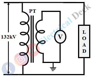
To measure high voltages, the primary winding of the potential transformer is connected across the transmission line to which voltage is to be measured. The working of a potential transformer is similar to a current transformer.
But the difference is that a current transformer is connected in series with the line, while the potential transformer in parallel. The secondary winding is usually rated for 110V is connected to a standard low range voltmeter as shown below.
Since less number of turns are wound on secondary. When the primary is connected to the high voltage line, it induces small voltages (ranging from 0-110V) in the secondary winding. These small voltages are then measured easily by normal voltmeters. A higher degree of insulation is done with secondary winding from the primary in addition to grounding to ensure operator safety.
Measurement of High Voltage using Potential Transformer :
By measuring the small voltage obtained at the voltage transformer secondary, we can determine high voltage in the transmission or distribution line. The voltage ratio of a potential transformer is defined as the ratio of primary voltage to secondary voltage.
Once the voltage ratio of a potential or voltage transformer is known, the voltage in the primary can be determined. For a transformer, the voltage ratio is given as,
If a potential transformer has a voltage ratio of 1200:1, and the voltage measured at the secondary V2 is 110 V. Then the voltage in the primary or high voltage line V1 will be,
Types of Potential Transformers :
There are two types of potential transformers namely, wound type potential transformer and capacitor voltage potential transformer.
The shell and core type potential transformers are called wound type potential transformers. The primary and secondary windings are wound on the core limbs with suitable insulation. But for measuring the voltages above 10kV, the construction of PT becomes complex due to insulation problems.
The drawback of conventional wound type potential transformer can be overcome by using capacitive PT, which uses a capacitive divider and auxiliary transformer. The use of a capacitive divider eliminates the use of high rating PT. The low voltage (below 10kV) obtained from the capacitive divider is further stepped down through an auxiliary transformer as shown below.
Errors in Potential Transformer :
Ratio Error :
Due to changes in the load conditions, the transformer's magnetizing and core loss components of the exciting current change. This causes a change in voltage ratio V1/V2 with respect to N1/N2. Thus, it affects the calculation of primary voltage with the given voltage ratio and causes an error. Such an error is called ratio error given as,
Where the nominal ratio is the rated primary and secondary voltage ratio (without the effect of magnetizing and core loss components ).
Phase Angle Error :
It is required to operate instruments or relays or pilot lights on the secondary of a PT. Due to its inductive nature, the secondary phase voltage which has to be displaced by exactly 180° from the primary voltage causes an error called phase angle error. By using high permeable core material with low reluctance, the errors in the potential transformer can be reduced.


