A phase-shifting transformer is a special type of transformer used to control active or real power flowing through a multi-network power system. It is used to stabilize power flow and balance the loads in the power system.
A phase-shifting transformer delivers a phase-shifted output power with a desired angle from the input power. The phase of the output quantity can be continuously varied keeping the magnitude constant. Let's see the construction and working of a 'Drysdale Phase Shifting Transformer'.
Construction of Phase Shifting Transformer :
The construction of the Drysdale phase shift transformer is similar to the induction motor. It consists of a stator winding kept stationary, and rotor winding that can be movable.
The stator of a phase shift transformer is wound with single or three-phase windings as seen in induction motors. The stator windings are kept on the stator slots of laminated silicon steel to reduce iron losses.
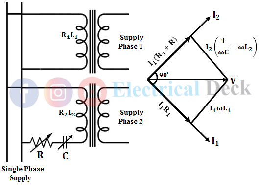
We know that single-phase induction motors are not self-starting motors because the rotating magnetic field is not produced by the single-phase supply. Similar to stator phase splitting in single-phase induction motors (i.e., split-phase induction motor), to produce a rotating magnetic field. The single-phase winding of a phase shift transformer is split into two windings (i.e., as two-phase winding) as shown below.
Now to produce a rotating magnetic field from this two-phase stator winding. There must be a phase difference in the magnetic field produced. For this purpose, a phase splitting device is used to produce a rotating magnetic field from the two-phase stator winding.
The two windings are arranged perpendicular two each other (90° apart). One of the stator winding is connected through a phase splitting device and the other directly across the supply as shown above.
The phase splitter is the combination of a series-connected variable resistor and capacitor. The resistance and capacitance of the phase splitter are adjusted till the winding in which it is connected produces a current displaced at 90° from other winding.
Therefore when the currents in the two stator windings are displaced at 90° and hence magnetic field. There produces a uniform rotating magnetic field by the two-phase stator winding.
Similar to the stator, the rotor winding is wound on laminated structured slots. To reduce leakage reactance, rotor winding is kept nearer to the stator winding. There exists a phase displacement in the induced emf according to the rotor rotation. The phase shift of the induced emf is proportional to the desired angle at which the rotor is rotated.
A pointer is attached at the top of the rotor rotated over the scale indicating the angle by which the rotor is rotated. The scale contains angles of phase displacement so that the required phase shift from the output can be obtained.
Working of Phase Shifting Transformer :
When single-phase supply is given to the two-phase stator winding displaced at 90°. It produces a uniform rotating magnetic field and links with the rotor conductors. The below shows the circuit of a two-phase stator winding with variable resistance and capacitance and the corresponding phasor diagram. This type of connection is called a quadrature winding arrangement.
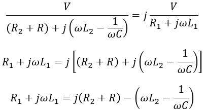
When the currents produced by the two-phase stator winding are displaced at 90°, then we have I2 = jI1,
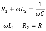
Equating real and imaginary parts,
Therefore, by varying R and C, required phase splitting is achieved to produce RMF. Rotor induced emf due to one stator winding is given by,
e1 = K I sin ωt cos θ
Rotor induced emf due to stator winding in which phase splitter is connected,
e2 = K I sin (ωt + 90°) cos (θ + 90°)
= - K I cos ωt sin t
The net emf induced in the rotor is given by,
e = e1 + e2
= K I sinωt cosθ - K I cosωt sinθ
= K I [sinωt cosθ - cosωt sinθ]
∴ e = K I sin (ωt - θ)
A required variable phase shift from the rotor output quantities can be obtained according to the rotor displacement. It can be seen that the rotor winding is arranged in such a way that change in phase shift doesn't affect the magnitude of the induced emf, and the phase shift depends upon rotor position i.e., θ.
Three Phase Shifting Transformer :
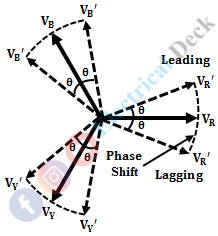
Similar to single-phase shifting transformers, three-phase shifting transformers are used where there is an availability of a three-phase supply. Compared to single-phase shifting transformers, three-phase shifting transformers are less sensitive to variations in frequency. The output of the three-phase shifting transformer is phase-shifted without changing the voltage ratio.
When the three-phase power is supplied to the phase shift transformer. By rotating the rotor with the desired angle, a phase-shifted output can be obtained without changing magnitude. The above shows the phasor diagram of phase-shifted output from the three-phase supply input. In order to obtain precise phase shifting, the rotor displacement is varied in discrete steps by an external motor.


