The increase in the transmission line lengths and the amount of power transmitted through the lines will result in rise of new problems in relation to the protection. This also leads to the rise of new techniques in order to handle these new problems.
A transmission line must ensure the continuity of the supply with the least possible interruptions, but at the same time, there is a need for shorter operating time protective relays on faulted sections to preserve the system stability. In order to meet these modern requirements, two major types of transmission lines schemes are used, namely,
- Distance relaying system
- Carrier current system or pilot wire system.
Due to the high cost and unreliability of the pilot wire system, it is not used for the protection of long transmission lines. Hence a distance relaying system is well suited for the protection of long transmission lines.
What is Distance Relay?
Unlike other relays whose operation depends upon the magnitude of current or voltage, the principle of distance relays is different. Its working is based on the fact that, when there is a fault in the transmission line, the distance between any point in the line and the fault that occurred is proportional to the ratio of voltage to current at the point. As the measured quantity is proportional to the distance along the line, the measuring relay is called the distance relay.
These are placed at various points along the transmission lines. On the occurrence of a fault, the relay measures the length of the line to the fault. Also, the operation of the relays is such that the nearest to the fault will operate quicker than other relays which are farther to the fault.
The various features offered by the distance relays are,- These are used for the protection of transmission and sub-transmission lines.
- These are operated at higher speeds to clear the fault.
- These are mainly used where the overcurrent relays become slow, and there is difficulty in grading time-over current relays.
- The measured quantity is proportional to the line length between the location of the relay and the point where the fault has occurred.
Working of Distance Relay Using 3-Zone Protection Scheme :
The below figure shows the 3-zone distance protection relay, i.e., the line section to be protected is mainly divided into 3-zone. The first zone unit is set to cover usually between 80 to 90% of the first section and is operated with an instantaneous high-speed relay. The second zone unit is set to cover about 25% of the second section and the third zone unit is set to cover up to the end of the second section with time-delay operated relays of T2 and T3 respectively.
Setting in the first zone for less than 100% (i.e, 80 to 90%) of the length is made to avoid the reach of the relay into the adjacent section. This overreach may occur due to the following.
- Errors in the relay.
- Errors in the CTs and PTs.
- Errors in the data on which the impedance settings are made.
The main purpose of the second zone unit is to provide protection to the end zone of the first section and also to give a remote back-up to the next section up to about 25% of its length. The time delay T2 operated in the second zone is normally between 0.2 and 0.5 seconds.
The third zone unit provides backup protection for faults in the adjoining line sections. As far its reach should extend beyond the end of the largest adjoining line section under the condition that causes the maximum amount of underreach. The time delay T3 operated in the third zone is usually between 0.4 seconds and 1.0 seconds.
Types of Distance Relay :
Distance relays are classified into two types for the protection of transmission lines. They are,- Definite Distance Relay (impedance, reactance, or mho type).
- Time Distance Relay (impedance, reactance, or mho type).
Definite Distance Relay :
Construction of Definite Distance Relay :
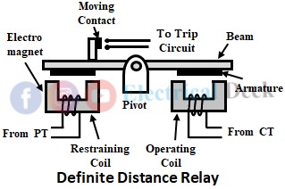
The constructional design of this type of relay can be a balanced beam-type or induction disc type that operates instantaneously for the fault up to a predetermined distance from the relay. The below shows the balanced beam type definite distance relay.
It consists of a balanced beam pivoted about its central point and two armatures of the two electromagnets attached at the two ends of the beam. Two electromagnets are placed below two armatures and are energized by current and voltage transformers respectively which are connected in the circuit to be protected. The beam is provided with a moving contact in order to close the contacts of the trip circuit. The design of the relay is in such a way that the torque produced by the two electromagnets are in the opposite directions.
Working of Definite Distance Relay :
Under normal conditions, the restraining torque i.e., the torque provided by the restraining coil due to the voltage element, is greater than that of the operating torque provided by the operating coil due to the current element and thus the relay contacts remain open. Hence the relay is inoperative.
When a fault occurs within the protected zone, the voltage applied to the relay decreases and the current increases i.e., the ratio V/I which is the impedance also decreases.
Once the ratio falls below the preset value, the operating torque prevails the restraining torque which in turn pulls the beam towards the operating coil side. This causes the moving contact to close the contacts of the trip circuit and thus the relay operates by opening the circuit breaker.
The torque produced by the voltage coil is proportional to V2 while that by the current coil is I2. The relay will operate when the torque produced by the voltage coil is less than that produced by the current coil. From this, we can write,
Where K1 and K2 are constants that depend on the ampere-turns of the two electromagnets. Thus, the setting value of the relay can be changed on the coil.
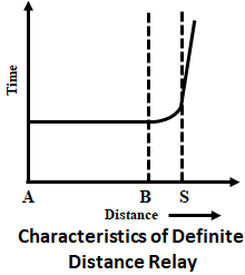
The above shows the characteristics of the definite distance relay. For the entire length AB of the line, the time of operation remains constant, irrespective of distance. But if a fault occurs in the section of line which is not protected, the operating time becomes suddenly infinite. Towards the end of the protected zone, the curve rises gradually. The quality of protection provided by the definite distance relays is superior to that provided by overcurrent relays, as the time of operation is the same for all relays.
Time Distance Relay :
Construction of Time Distance Relay :
In a time distance relay, the operating time of the relay is proportional to the distance of fault from the relay point. The operating time for the faults nearer to the relay is less compared to the faults away from the relay. Thus,
The construction of a time distance relay is similar to the induction type overcurrent relay with two current-driven electromagnets with a rotating disc between them. The spindle that carries the disc is attached to another spindle by a spiral spring coupling. The below shows the schematic arrangement of the time distance relay.
The moving contact is connected to the upper spindle which closes the trip circuit when comes under contact with trip circuit contacts. The trip circuit is normally kept open by placing the upper spindle at a position by an armature against the pole face of an electromagnet (restraining coil) excited by the voltage of the circuit to be protected.
Woking of Time Distance Relay :
When there is no fault in the line i.e., under normal operating conditions, the force exerted by the restraining coil will be greater than the force exerted by the operating coil. This doesn't allow the upper spindle to rotate and it remains at the same position holding moving contact away from the trip circuit. Thus the trip circuit is left open in normal conditions i.e., the relay is inoperative.
When a fault occurs, the disc starts rotating and it also rotates the spindle which carries it. The rotation of the spindle causes the spiral spring to wound up till the tension of the spring is sufficient to pull the upper spindle from the force exerted by the pole face of the restraining coil.
Once the force exerted by the operating coil becomes greater than the restraining coil. The upper spindle starts rotating and closes the trip circuit by making moving contact in contact with the trip circuit contacts and thus opens the circuit breaker to isolate the faulty section.
The angle through which the disc must rotate to close the trip contacts (i.e., to pull the upper spindle) depends on the force exerted by the restraining coil on the upper spindle.
This force is thus proportional to the voltage of the system. The greater this force, the greater will be the travel of the disc. So rotation of the disc is proportional to the system voltage. But the time that the disc takes to rotate through a certain required angle varies inversely with the operating current.
But generally, the force exerted by the restraining coil is proportional to the V. While the torque produced on the disc is proportional to I. Hence the time distance characteristics of this relay are nonlinear in nature, as shown above. This type of relay has an operating time of 0.2 seconds.


