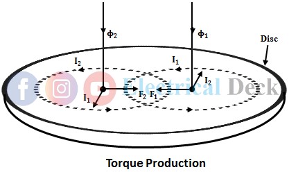
The induction relay works on the principle of electromagnetic induction similar to the induction motor and energy meter. It consists of two electromagnets and a rotating disc placed between the two electromagnets. The torque produced in these relays is by the interaction of alternating flux with the eddy currents induced in the rotor (disc) by another alternating flux.
The two electromagnets when excited produce two alternating fluxes Φ1 and Φ2. The two fluxes produced by the electromagnets will be of the same frequency but there exists a phase displacement α (required for the production of torque) between the two fluxes. The mathematical expression for the two alternating fluxes is given by,
The two alternating fluxes when links with the disc induce two emfs in the disc which lags their respective fluxes by 90°. The induced emfs leads to the circulation of eddy currents i1 and i2 in the disc. The interaction of eddy currents produced due to two alternating fluxes results in the production of force or torque in the disc.
The above figures show the production of force or torque in the disc of an induction relay. The eddy currents will be in phase (assuming the disc to be non-inductive) with their respective induced voltages. The induced voltages are proportional to the rate of change of fluxes and hence the eddy currents are also proportional to the rate of change of fluxes. Hence we can write,
Substituting Φ1 and Φ2 from equations 1 and 2 in the above equations, we get,
The force or torque produced on the disc is due to the interaction of Φ1 with i1 and Φ2 with i2.
∴ F1 ∝ Φ1 i2
and F2 ∝ Φ2 i1
The directions of F1 and F2 can be found from the Flemings left-hand rule. From the above figure, it can be seen that the two forces are acting in opposite directions. Hence the resultant force acting on the disc is given by,
F ∝ F2 - F1
∴ F ∝ Φ2 i1 - Φ1 i2 ...(5)
Substituting the expressions of Φ1, Φ2, i1, and i2 from equations 1, 2, 3, and 4 in equation 5, we get,
F ∝ [Φ2m sin(ωt + α) Φ1m cos ωt - Φ1m sin ωt Φ2m cos(ωt + α)]
F ∝ Φ1m Φ2m [sin(ωt + α) cos (ωt) - sin ωt cos(ωt + α)]
F ∝ Φ1m Φ2m [sin(ωt + α - ωt)]
∴ F ∝ Φ1m Φ2m sin α
The above equation gives the resultant force or torque produced in an induction relay. By considering rms values of the alternating fluxes, the above equation is expressed as,
From the above equation, it can be seen that if the two fluxes are in phase with each other. The net torque produced will be zero and the disc cannot rotate. Hence in order to operate an induction relay, there must be phase displacement between two fluxes and the maximum torque produced in the disc is when the phase difference between two fluxes is 90°.
The torque produced will be of constant magnitude and the direction of torque will depend upon the alternating flux that leads the other. A spring is used to produce control torque, while the damping torque is produced by a permanent magnet. There are various constructional designs (e.g. shaded pole type) of induction relay used to displace the fluxes for the production of torque.


