We know that there are different types of dc generators based on how the field and armature terminals are connected. They are,
- Separately excited d.c. generator.
- Self-excited d.c. generator.
- Shunt generator,
- Series generator,
- Compound generator.
Let us check out the characteristics and performance of these generators.
- Shunt generator,
- Series generator,
- Compound generator.
Characteristics of Separately Excited DC Generator :
In a separately excited dc generator, field windings are energized by a separate external source, rather than using the same supply used to supply the armature.
No-Load Characteristics :
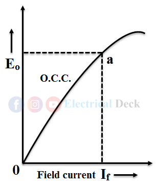
It shows the relation between no-load generated emf Eo and the field current at a given speed. It is also known as magnetization characteristics or open-circuit characteristics (O.C.C.).
No-load emf,
Where,- K = constant = ZNP/60
- Eo ∝ field current
- φ ∝ field current
It is clear from the above expression that when the field current is increased by varying the potential divider from zero, the flux φ and hence Eo increases. The readings of Eo and field current should be tabulated and the relation between the two should be plotted. The flux increases until the poles become saturated, after that a greater increase in field current is required to produce a given φ and hence Eo.
That is why the upper portion of the curve bends over as shown. The O.C.C. is useful in finding the required voltage, Eo of the generator at any particular conditions such as no-load and speed.
Load characteristics :
The relation between the e.m.f. actually induced, E and the armature current Ia gives the Internal characteristics.
At first, the generator should be brought up to its rated speed and then the field should be increased until the voltmeter reads rated voltage. Now the switch S2 is closed. Then the initial readings of load current (i.e., O at this instant) and V should be recorded and tabulated. Now the load is adjusted to increase load current. The load resistance should be decreased further, until the ammeter, load current reads full load current or as desired.
Now the graph between V and load current should be plotted by curve ab. This is known as load or external characteristic curve. It can be noticed from the graph that the voltage decreases slowly with an increase in load current. While taking the readings the generator speed should be maintained constant by varying the prime mover speed.
The voltage recorded at zero load current is Eo. It is parallel to abscissa (X-axis) and is shown by dotted lines because on no-load current is zero. Now determine Ia Ra drop at every reading and add to the load curve. Thus the curve obtained is ac and is known as internal characteristics. The relation between the terminal voltage V and load current IL gives the external characteristics.
Characteristics of Self-excited DC Generators :
i. Characteristics of DC Shunt Generator :
In a dc shunt generator, the field winding is connected across (parallel) the armature terminals and the armature current Ia produced is the sum of field current Ish and load current IL.
No-load Characteristics :
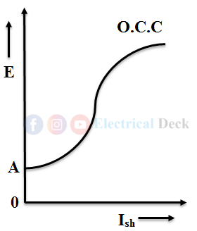
No-load or open circuit characteristics of a shunt generator are obtained by plotting ammeter reading (field current) i.e. Ish, versus voltmeter reading E (generated voltage).
Under the no-load condition, the generator is said to be open-circuited and rotating at a constant speed. From the EMF equation of dc generator, generated voltage E is directly proportional to flux φ. As φ is directly proportional to field current Ish, an increase in Ish also increases E.
Also if there is no field current Ish at starting, we can notice some voltage E in the armature. This is mainly due to magnetism present in the field poles, known as residual magnetism. That is why the graph starts from point A but not from origin 0.
Now as the field current Ish, flux φ, increases with an increase in voltage E. But, after reaching certain current Ish the field gets saturated and therefore φ and E remain constant as shown in the above figure.
Load Characteristics :
When a shunt generator is loaded, voltage builds up, then its terminal voltage drops due to armature resistance and armature reaction. The terminal voltage V and load current IL can be measured, the relation between these V and IL can be drawn like (a-b), known as the external characteristic curve.
If armature resistance drop components are added to the curve (a-b), we get the internal characteristic curve (a-c), as shown. If armature reaction drop components are added to this curve ac we get curve or line (a-d), which can be called no-load characteristics, but on no-load the IL = 0. Therefore it is imaginary and hence shown with a dotted line.
If it is increased beyond the rated value, the terminal voltage decreases rapidly due to increased armature reaction, represented by the curve (b-e). It is known as drooping characteristics.
ii. Characteristics of DC Series Generator :
In a dc series generator the field winding, armature, and load are connected in series with each other i.e., IL = Ise = Ia.
No-load Characteristics :
The no-load characteristics of a dc series generator are similar to the no-load characteristics of a shunt generator. But, at no-load condition, the generator is running at a constant speed due to series connection no field current flows as the load current IL, is zero. Hence it is difficult to obtain no-load characteristics.
To draw the O.C.C. of a series generator the field winding should be given a separate d.c. supply. The diagram below shows the O.C.C. of a separately excited series generator.
Now if the field current IL, increases the voltage E will also build up proportionally. Here also the curve starts from point A due to residual magnetism.
Load Characteristics :
When the series generator is loaded it starts drawing the current. Here, we know that IL = Ise = Ia. So as the load current IL increases e.m.f. induced E also increases. The curve a-c between IL and E shows internal characteristics. This curve lies below the curve of O.C.C. due to the armature reaction effect.
The external characteristics are shown with a curve, it lies below the internal characteristics due to a drop in armature and field windings. From the curves obtained we notice that an increase in IL, increases E. Therefore, the series generator characteristics are also called Raising Characteristics.
iii. Characteristics of DC Compound Generator :
A compound generator or compound wound generators is a combination of both shunt and series wound generators. One winding is connected in series and the other is connected in parallel with the armature.
Load Characteristics :
A shunt generator can be made to supply a constant voltage by connecting a few turns in series with the armature terminals. This arrangement is known as a compound generator. There are two types of connections for connecting a series and shunt windings in a compound generator.
If the connection is in such a way that flux produced by both series and shunt windings (φse and φsh) are both in the same direction then the connection is said to be a Cumulative Compound. If the connection is in such a way that both the fluxes (φse and φsh) produced, are opposite to each other, then it is known as Differential Compound. The below figure shows the two different connections of a compound generator.
Now, in a compound generator when load current IL increases. The current Ise in series turns also increases which in turn produces more flux and thereby generating more e.m.f. But due to increase an in armature current Ia, there will be an increase in voltage drop due to armature resistance and armature reaction.
If the series field turns are such as to produce e.m.f. equal to drop due to armature resistance and armature reaction, then the generator is called flat compounded or level compounded.
If the series field turns produce e.m.f. more or less than the drop due to armature resistance and reaction, then the generator is called over compounded or under compounded respectively.


